He found a resonant peak on that transformer.
No, I found resonant notches where the leakage inductance and the winding capacitance combine to create a HF notch in both the 1628SE and the 1628SEA. I never tried the 1642SE due to the cost.
I have asked around the forum several times over the years to see if anyone has used it for a big SE amp, and never got a valid response. One user claimed to have used this monster for an 8 watts amp with "excellent results" but took no measurements. Another user later bought one, took measurements, and did not like the results......same notch.
That thread is here:
http://www.diyaudio.com/forums/tube...42se-big-se-amp.html?highlight=Hammond+1642SE
The resonant notch is common in many OPT's but usually occurs well above the audio range, such that it does not affect the frequencies in the 10 KHz to 20 KHz range. The 1628SE places the notch at about 20 KHz causing a 6 db drop at 15 KHz. The 1628SEA was better, but I don't remember the exact numbers. The depth of the notch is controlled by the circuit "Q." This is a parallel resonant circuit, with the plate resistance of the output tube one of the parallel elements. The higher the Rp, the higher the Q and the deeper the notch. The 833A has a very high Rp.
Where do you get your Custom OPT?
It was a one of a kind, made by Transcendar. I paid for time and material, since both of us agreed up front that it was an experiment. It worked better than either of the Hammonds, but not quite HiFi quality performance. Looking back now, I probably could have made it work with some feedback, perhaps through the cathode.
No, I found resonant notches where the leakage inductance and the winding capacitance combine to create a HF notch in both the 1628SE and the 1628SEA. I never tried the 1642SE due to the cost.
I have asked around the forum several times over the years to see if anyone has used it for a big SE amp, and never got a valid response. One user claimed to have used this monster for an 8 watts amp with "excellent results" but took no measurements. Another user later bought one, took measurements, and did not like the results......same notch.
That thread is here:
http://www.diyaudio.com/forums/tube...42se-big-se-amp.html?highlight=Hammond+1642SE
The resonant notch is common in many OPT's but usually occurs well above the audio range, such that it does not affect the frequencies in the 10 KHz to 20 KHz range. The 1628SE places the notch at about 20 KHz causing a 6 db drop at 15 KHz. The 1628SEA was better, but I don't remember the exact numbers. The depth of the notch is controlled by the circuit "Q." This is a parallel resonant circuit, with the plate resistance of the output tube one of the parallel elements. The higher the Rp, the higher the Q and the deeper the notch. The 833A has a very high Rp.
It was a one of a kind, made by Transcendar. I paid for time and material, since both of us agreed up front that it was an experiment. It worked better than either of the Hammond, but not quite HiFi quality performance. Looking back now, I probably could have made it work with some feedback, perhaps through the cathode.
Thanks for the clarification, George! I mis-remembered it and mixed up your custom made one with the 1642SE and with the other guy's measurement on the 1642SE. I reread your thread from the beginning to end and see what's going inside my head. Too many works and too much readings. whew...
3dB drop anywhere on the AF band would be a real concern. 6dB is out of the question!
Hi Guys
If this is an SE amp, I believe you should be using the CCS rating of 300W rather than the ICAS 350W. (natural cooling) A small hit on maximum output power but efficiency here is of no concern. Adding a fan would allow using the 400W CCS rating but fan noise in a hifi system is plain wrong.
For the 1642SE, a peak current of 173mA at 866Vpk gives the 150W peak output. The 833 should be loafing driving this load.
Have fun
hello my GM70SE have 1629SEA and its perfect, no problemsNo, I found resonant notches where the leakage inductance and the winding capacitance combine to create a HF notch in both the 1628SE and the 1628SEA. I never tried the 1642SE due to the cost.
I have asked around the forum several times over the years to see if anyone has used it for a big SE amp, and never got a valid response. One user claimed to have used this monster for an 8 watts amp with "excellent results" but took no measurements. Another user later bought one, took measurements, and did not like the results......same notch.
That thread is here:
http://www.diyaudio.com/forums/tube...42se-big-se-amp.html?highlight=Hammond+1642SE
The resonant notch is common in many OPT's but usually occurs well above the audio range, such that it does not affect the frequencies in the 10 KHz to 20 KHz range. The 1628SE places the notch at about 20 KHz causing a 6 db drop at 15 KHz. The 1628SEA was better, but I don't remember the exact numbers
hello my GM70SE have 1629SEA and its perfect, no problems
Hi,
Did you run a sweep of the GM70 and no dip / notch found? Something along the production may have changed.
Is the one you made by Hammond Canada or some other country?
Hi Guys
If this is an SE amp, I believe you should be using the CCS rating of 300W rather than the ICAS 350W. (natural cooling) A small hit on maximum output power but efficiency here is of no concern. Adding a fan would allow using the 400W CCS rating but fan noise in a hifi system is plain wrong.
For the 1642SE, a peak current of 173mA at 866Vpk gives the 150W peak output. The 833 should be loafing driving this load.
Have fun
I like Natural Air cooling but the fan cooling might be fine if you can push some air from the bottom of the chassis. There are really very quiet DC fans around 7dB noise so you'll hardly hear anything when it's installed under the chassis. I guess the best way to run this tube for HiFi is to use some kind if Glass Chinmey like in Eimac tubes and run a very quiet fan underneath. The CFM is low on these quiet fans but you only need some ventilation so should be enough.
150W (Peak?) about 100W RMS Power from the Transformer requires about twice the size of that Hammond, may be?
just done a sweep 20/20KhzHi,
Did you run a sweep of the GM70 and no dip / notch found? Something along the production may have changed.
Is the one you made by Hammond Canada or some other country?
this amp have economic plate choke 20mA on 6L6 and pio 1uf cap
transformer made in canada
the last i made with sowter IT and powerfull psu its much better linear OPT 10K 1638SEA
Attachments
Last edited:
just done a sweep 20/20Khz
this amp have economic plate choke 20mA on 6L6 and pio 1uf cap
transformer made in canada
the last i made with sowter IT and powerfull psu its much better linear OPT 10K 1638SEA
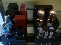
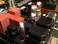
First of all, Nice Amp! Love how that GM70 glows.
Are you sweeping the FR through the speakers? I am seeing a roll off from 10K-20K but it's probably due to the speakers off axis response and in room response if sweep through the speakers.
no speaker, 8ohm 200watts dump resistor, tascam us366 card but pentium3 pc!First of all, Nice Amp! Love how that GM70 glows.
Are you sweeping the FR through the speakers? I am seeing a roll off from 10K-20K but it's probably due to the speakers off axis response and in room response if sweep through the speakers.
this morning i swap 6l6gc to 6L6GA sylvanya, little better.
i do not have sweep of my last one but was much better opt10K 1638SEA sowter IT
Attachments

Last edited:
I found some of my old test data from nearly 10 years ago.
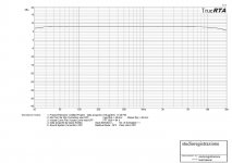
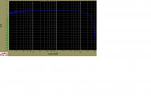
The first picture is of a Hammond 1628SE. This is the original design with two separate secondaries that must be interconnected to provide the desired impedance. The 8 ohm connection was used. The test was run in UL mode with no feedback applied. Output tube was a Sovtek KT88. The resonant notch can be seen at 40 KHz and is about 30 dB deep. This notch is highly dependent on the Rp of the tube, and will be worse with a tube having a higher Rp. The notch at 40 KHz results in a rolloff starting at 10KHz and is about 4.5 db down at 20 KHz.
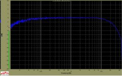
The second picture is a Hammond 1628SEA. This version has the single tapped 0-4-8-16 ohm secondary. It is better. The notch has moved out to about 50 KHz, but there is still 3 dB of rolloff at 20 KHz.
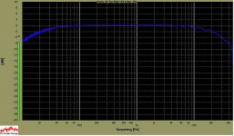
The third picture is an early version of the big Edcor OPT. The notch is out beyond my measurement limit of 48KHz. I'm guessing 55 to 60 KHz. Listening tests show the newer versions to be better, but I have not tested one.
The first picture is of a Hammond 1628SE. This is the original design with two separate secondaries that must be interconnected to provide the desired impedance. The 8 ohm connection was used. The test was run in UL mode with no feedback applied. Output tube was a Sovtek KT88. The resonant notch can be seen at 40 KHz and is about 30 dB deep. This notch is highly dependent on the Rp of the tube, and will be worse with a tube having a higher Rp. The notch at 40 KHz results in a rolloff starting at 10KHz and is about 4.5 db down at 20 KHz.
The second picture is a Hammond 1628SEA. This version has the single tapped 0-4-8-16 ohm secondary. It is better. The notch has moved out to about 50 KHz, but there is still 3 dB of rolloff at 20 KHz.
The third picture is an early version of the big Edcor OPT. The notch is out beyond my measurement limit of 48KHz. I'm guessing 55 to 60 KHz. Listening tests show the newer versions to be better, but I have not tested one.
Attachments
just done a sweep 20/20Khz
this amp have economic plate choke 20mA on 6L6 and pio 1uf cap
transformer made in canada
the last i made with sowter IT and powerfull psu its much better linear OPT 10K 1638SEA
I experience the same drop with my Hammond
With horns, it's clearly noticeable so I'm looking to replace mine
no speaker, 8ohm 200watts dump resistor, tascam us366 card but pentium3 pc!
this morning i swap 6l6gc to 6L6GA sylvanya, little better.
i do not have sweep of my last one but was much better opt10K 1638SEA sowter IT
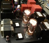
3b28? 😀
3b28?
That's what they look like to me. Mine glowed a bit whiter than those, but different cameras record the infrared differently. Mine makes dark plates look like they are glowing pink.
Gents,
I have been thinking. Before we put any blame on the OPT, isn't it better to just sweep the OPT out of the circuit with the Function Generator and a scope for the basic FR curve?
The in circuit measurements seems the roll off from Triode Output tube due to the high capacitance value. It may be masking any OPT dib and recovery or there is none at all with those OPT.
George,
I always see notches like these on the Tango/Tamura SE OPT too but I didn't save the curves so I don't remember where they are at. But they are usually beyond 40KHz so I don't really have to care.
isn't it better to just sweep the OPT out of the circuit with the Function Generator and a scope for the basic FR curve
In theory, yes. The custom OPT that I had made was tested by the manufacturer that way, and so are the Hammonds when they are built.
Most function generators are specified to operate into a 50 ohm or 600 ohm load, while their actual output impedance may be much lower. The old tube type Hewlett Packards had a real output impedance of about 30 ohms. We used them in the factory to drive test speakers directly.
The resonant notch we see in real world operation of a vacuum tube amp is a parallel resonance. The Rp of the tube (or the output impedance of the generator) is in parallel with the resonance formed by the OPT's leakage inductance and it's winding capacitance (and a few other L's and C's).
The "Q" of this resonant notch is the ratio of the resistive (tube Rp or generator) component and the reactive (inductive and capacitive) component. If the source impedance is low (as it is with a generator) the notch will be broad and not very deep. If the source impedance is high (Rp of a tube) the notch can be sharp and deep. My pictures were made with a KT88 in UL or triode with no feedback.
From the manufacturers standpoint, they want to test the OPT with a function generator having a near zero output impedance.....the notch won't even show up since it is "de Qed by the low impedance source. This, however is not how the OPT will be used in the real world.
As I have argued for 40 years as a design engineer at Motorola, we really need both, and we need to understand what we are measuring, and how we are actually going to use what we are testing. All the double blind, and statistically accurate testing in the world may not help you find the right component for your design if you aren't looking at the parts correctly. Specs shown on data sheets are often made under ideal conditions.
The 833A, most pentodes, and most other high Mu triodes have a rather high Rp. This will bring out the worst in the OPT, especially those with higher than average stray capacitances and inductances. Feedback and other methods to lower the impedance that the OPT is driven by will go a long way to make an OPT work better, but can't cover up a bad design.
About 12 years ago I made an amp that I call the 300Beast. It was a push pull 300B amp using the new at the time Sovtek 300B. It was an experiment just to see what works. I used junk box parts and a pair of guitar amp quality OPT's that I got for $16 each. I bought 200 of them to make guitar amps. That amp sounded REALLY NICE, but defied all attempts to upgrade it with good parts. Vintage UTC OPT's, boutique caps, fancy resistors.....nothing made it sound better, and many things made it worse, so it remains today just as it was made 12 years ago. It's still one of the most dynamic sounding amps I have ever made.
After 12 years of experimenting with those OPT's and taking one apart, I now understand what I stated above. Those OPT's work great when fed with a low impedance source. The best cases have been a 300B (Rp about 800 ohms) and a sweep tube with Schade feedback wrapped around it. A triode wired KT88 worked reasonably well, but a pentode wired EL84 even with GNFB was just OK. In the good cases, the frequency response, and the maximum power before saturation were better than, say the EL84 amp.
So, yes we can, and do test OPT's with a 600 ohm function generator, but to decide which OPT to use in a given circuit, requires testing them in that circuit, or having an excellent computer model (which doesn't exist in our world) and doing a computer analysis.
At Motorola we had the "simulation and calculation" people, and the "build it and test it" people. Both served valid functions, but we were often at odds with each other. Usually it was because the simulation people didn't fully understand the real world applications.
I can remember one of my arguments about a two way radio..... (me to a seasoned engineer) Do you understand what 1 MEGAWATT of RF power is? Do you realize that those TV towers right next to the Miami Dolphins NFL stadium have 7 transmitters EACH cranking out 1 MEGAWATT of amplitude modulated digital noise? One is only 30 MHz away from your receive frequency and you have a plastic cased radio with no shielding over the filters......Boss man, can you organize a field trip to a football game? We want the nose bleed seats on the upper deck in the east end zone (closest to the towers). He did. Their little prototype radio did not receive anything from a guy with a similar radio inside the same stadium.....That ended the direct conversion experiments. I can relate hundreds of similar events from a 41 year career there.
Very interesting.. Great explanation. So that begs the question, who is making output transformers right now that would even be suitable for this type of amp, utilizing tubes that have a high Rp?
I know Mags got an insane pair of output transformers from Monolith which worked out great.. And in fact I'm using a pair of S-5 output transformers from Monolith with my 845 SET amp as well (which sound great)..
But who else?.. Maybe someone slightly more budget friendly?..
I was looking for a "budget" choice and that didn't work out too well, but it worked far better than any of the Hammonds that I tested and cost me $200 8 to 10 years ago. Looking back now I should have bought a second one. The way my hearing is today anything over 15 KHz is masked by the constant tinnitus. I have a huge power transmitter out of a Harris radio transmitter, so all the parts are present for a single channel.....maybe I will build that killer guitar amp.
An OPT of this magnitude requires some serious interleaving and someone that really knows what they are doing. Anything built to a price point will be a compromise, but then EVERY OPT is a compromise. Some just have fewer variables to juggle, like cost, size and weight.
An OPT of this magnitude requires some serious interleaving and someone that really knows what they are doing. Anything built to a price point will be a compromise, but then EVERY OPT is a compromise. Some just have fewer variables to juggle, like cost, size and weight.
I was looking for a "budget" choice and that didn't work out too well, but it worked far better than any of the Hammonds that I tested and cost me $200 8 to 10 years ago. Looking back now I should have bought a second one. The way my hearing is today anything over 15 KHz is masked by the constant tinnitus. I have a huge power transmitter out of a Harris radio transmitter, so all the parts are present for a single channel.....maybe I will build that killer guitar amp.
An OPT of this magnitude requires some serious interleaving and someone that really knows what they are doing. Anything built to a price point will be a compromise, but then EVERY OPT is a compromise. Some just have fewer variables to juggle, like cost, size and weight.
I wonder though, who even makes something suitable? Even at a realistic price. I haven't really found anything other than that Monolith transformer.
Another amp to look at . I remember reading something that indicated it wasn't running the 833 at a very high voltage but now can't remember what that V was. Maybe you can work it out from given specs.
Link1 Link2
You might also be interested in the Schaded stuff. I built up this circuit by Michael Koster and though it needs work it sounded good enough out of the chute to be left without disassembly on the back of the shelf for a day when I have time , inclination and the knowledge to raise the bar a little. Michael claimed the effective rp of the tube was down to 4-500 Ohms. I've been trying to test that but so far have got inconsistant results.
It's easy to hear though that the approach has a lot of potential. . . . or so I think anyway.
- Status
- Not open for further replies.
- Home
- Amplifiers
- Tubes / Valves
- 833A "budget" design