Very handsome. Unfortunately I will not be here to congratulate you, as
I will be out of town.
🙁
I will be out of town.
🙁
Very handsome. Unfortunately I will not be here to congratulate you, as
I will be out of town.
🙁
Your encouraging words are much appreciated. My resistor checkout went without a hitch. I hope the voltage check goes as well. If not I will not fill your inbox but rather cry on this forum for advice.
Great pic! I'm still a bit uneasy about the resistor proximity. There is a corresponding 47uF 25V Silmic II that has the right lead spacing and is 6mm diameter. What's a healthy cap voltage spec for this part - is 25V enough?
Are any locations actually better suited for a good non-audio grade cap such as Panasonic FC?? I get a warm fuzzy whenever I see long-life 105C caps with lots of voltage headroom...
BK
You can solder resistors around C3 in vertical position if 10 mm cap....Silmic II are great 🙂
Best regards
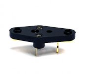
Judging from the pic Nelson posted earlier in post #1608 http://www.diyaudio.com/forums/pass-labs/276711-sony-vfet-amplifier-part-2-a-33.html#post4801837 it appears that Bourns 3386 single turn Cermet potentiometers can be used.
Edit: Looking at the pinout as seen in post #1725 http://www.diyaudio.com/forums/pass-labs/276711-sony-vfet-amplifier-part-2-a-35.html#post4807555 the 3386P type will fit.
Edit: Looking at the pinout as seen in post #1725 http://www.diyaudio.com/forums/pass-labs/276711-sony-vfet-amplifier-part-2-a-35.html#post4807555 the 3386P type will fit.
Last edited:
After the fun I had biasing an F6 with single turn parts, I'd strongly suggest multitude parts... 🙂
I will certainly be using multiturn parts if and when I ever get one of these kits. Sorry to say that there is still no information forthcoming to those of us on the group 2 list.
____________________________________________________________
BOZ, BA-3 Preamp, F4, F5, JLH1969, JLH1996/2003, JLH1970s75W
____________________________________________________________
BOZ, BA-3 Preamp, F4, F5, JLH1969, JLH1996/2003, JLH1970s75W
We've worked out the quantity with Nelson on the next batch, we just need to get info on how long it will take him to do the matching. He's a busy guy. However during the time he's matching we'll be getting the rest of the kit parts ready.
I will certainly be using multiturn parts if and when I ever get one of these kits. Sorry to say that there is still no information forthcoming to those of us on the group 2 list.
____________________________________________________________
BOZ, BA-3 Preamp, F4, F5, JLH1969, JLH1996/2003, JLH1970s75W
We've worked out the quantity with Nelson on the next batch, we just need to get info on how long it will take him to do the matching. He's a busy guy. However during the time he's matching we'll be getting the rest of the kit parts ready.
Thanks for the reply, I assume from this that we will be in line to receive something from batch 2. Looking forward very much to that.
____________________________________________________________
BOZ, BA-3 Preamp, F4, F5, JLH1969, JLH1996/2003, JLH1970s75W
And oversized Silmic 2 make my heart all fuzzy
So about the pots: one turn or multi- turn?
If its going to be multi-turn, how about the least amount of multi-turn you can get? 10x pots suck for this sort of thing.

Single trimmers are easy to operate and we have visual control from outside.
Ok need some practice & experience to avoid to much resistance jump mouvements.
Multiturns are precise & slow to regulate
guess is more safe for not professionals electronicians like me 😀
***** Full counter clockwise for P3 and P4 *****

Ok need some practice & experience to avoid to much resistance jump mouvements.
Multiturns are precise & slow to regulate
guess is more safe for not professionals electronicians like me 😀
***** Full counter clockwise for P3 and P4 *****
Attachments
-
 7ADDB00D-160A-48A3-A1B8-E45597872B7E.JPG27.1 KB · Views: 635
 -
 8E50E02D-6A97-4AB0-8127-5B105F48D9DD.JPG24.7 KB · Views: 642
 -
 52C2C284-D749-4BAA-87C5-9F02ED77141A.JPG21.8 KB · Views: 636
 -
 0555E654-E7DE-4BFB-B2FB-FFB0292B768F.JPG20.3 KB · Views: 630
 -
 CC3F69FC-99E4-4900-BB5C-96A607A43DA2.JPG47.5 KB · Views: 253
I've got the kit!
Many thanks to everyone for their efforts that have made this possible for us.
Many thanks to everyone for their efforts that have made this possible for us.
Jason
Do those of us who are at the end of the group 2 list assume that we are not getting a kit from the first batch? I have had no email to say one way or the other and there has been no information posted here for a while. Will we be getting something from the second batch?
Sorry for any lack of communication.
I have been trickling out orders for group 2 slowly so the order of signing up was respected. As of today, we have officially sold out of kits. In the coming weeks we will start pre-selling batch 2 and offering them in the following order:
- People from group 1 that gave up their spots
- People from group 2 that gave up their spots
- People from group 2 that didn't get a chance the first time around, in order of signing up
- General public
Received my kit. Thanks. I remember there was talk about having just brackets or pcbs available. Is that still the case. I would like to get an extra set or two of the brackets so I can build some se amps with my original vfets.
No problem ordering (extra) brackets or PCBs. Just email contact@diyaudiostore.com and they'll make you up a special order.
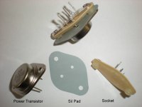
I have ran into a problem with my test. The voltage at G-T1 is -28 instead of -24V. The corresponding G-T2 is correct G-T2 +24. Also I cannot get enough bias on the V-fets. The pots, P1 and P2, reach their limit before 100 mv is reached. The V-fets never get warm. When biasing up the front end the only way I could achieve 0 offset was to set the voltage drop across R5 and R6 at .9V. At 1.2V the offset could not be lowered. I am using jfets 8's from the store and iffy 2SJ313 and 2SK2013 I just purchased. I say iffy because one can never be sure with obsolete parts unless you test them yourself.
I hope I have stated and tested everything correctly. This is only one channel. I am doing one at a time as instructed.
I hope I have stated and tested everything correctly. This is only one channel. I am doing one at a time as instructed.
Which version of the draft are you using for reference?
I think there was a typo in the earlier version labeled "1st draft 6/27/16". In the 1st draft G-T1 was accidentally specified with having -24V. The updated 2nd draft correctly states G-T1 as having -28V.
You want to bias the frontend to G-T4 reading -24V, as correctly stated in the 2nd draft. The frontend can be biased without the VFETs installed.
TL;DR/PSA: Use the updated 2nd draft of the DIY Sony VFET article.
Many thanks. I was sure I was using the 2nd draft but I was wrong, I have been using the 1st draft. This forum is wonderful.
I have already installed the V-fets and I still need help solving the bias problem of the V-fets. I will run the voltage checks with the 2nd version instructions and see if they are correct. With my very limited understanding I see the problem as being in the Q5 and Q6 circuit. I have already ordered Fairfield mosfets in case they are needed along with A TL431's and different pots.
I have already installed the V-fets and I still need help solving the bias problem of the V-fets. I will run the voltage checks with the 2nd version instructions and see if they are correct. With my very limited understanding I see the problem as being in the Q5 and Q6 circuit. I have already ordered Fairfield mosfets in case they are needed along with A TL431's and different pots.
Last edited:
Sorry for any lack of communication.
I have been trickling out orders for group 2 slowly so the order of signing up was respected.
Thanks Jason, just what we needed. The work that you guys have put into this project is of course greatly appreciated, together with Nelson Pass who has freely given us the design in the first place and made available the semiconductors. I'm just hoping that I will be lucky!
Regards John
______________________________________________________
Boz, BA-3 preamp, F4, F5, JLH1969, JLH1996/2003, JLH 1970s75W
I am using jfets 8's from the store and iffy 2SJ313 and 2SK2013 I just purchased. I say iffy because one can never be sure with obsolete parts unless you test them yourself.
You should be able to check Vgs vs Id easily enough using a couple points from the datasheet. I bought some iffy J313/K2013 a while back and did just that. For instance, with 2.5Vgs and 12Vds, they should pass about 300mA of current. My iffy FETs were completely off with these conditions, and they did not conduct until Vgs was raised above 4V. Might be something worth checking if your front end is not performing quite right.
Which version of the draft are you using for reference?
I think there was a typo in the earlier version labeled "1st draft 6/27/16". In the 1st draft G-T1 was accidentally specified with having -24V. The updated 2nd draft correctly states G-T1 as having -28V.
You want to bias the frontend to G-T4 reading -24V, as correctly stated in the 2nd draft. The frontend can be biased without the VFETs installed.
TL;DR/PSA: Use the updated 2nd draft of the DIY Sony VFET article.
Just so that I am sure is this the 2nd draft you refer to:
http://www.firstwatt.com/pdf/art_diy_sony_vfet_1st_draft.pdf
Thanks.
- Home
- Amplifiers
- Pass Labs
- Sony vFET Amplifier Part 2