I use 0,1 ohms on top anode, it is ok. Forget dabout miliampermeters, they are decorative eventualy.....I don't trust my cheap moving-coil milliameters so I'm going to put a small resistor in the anode or cathode connections to one or other of the O/P tubes and take leads to some Hirschmann 2mm measurement probe sockets. This will also make the measurements much more accurate.
I'm thinking of resistors of either 1.0 or 0.1 Ohms. Any suggestions about the value without affecting the performance?
Yes, thanks. Is it Ok to use a 1.0 Ohm, as it will give an extra decimal place of accuracy with the digital voltmeter? 205 mA would read .02 Volts with 0.1 Ohm, whereas it would read .205 with a 1.0 Ohm resistor.I use 0,1 ohms on top anode, it is ok. Forget dabout miliampermeters, they are decorative eventualy.....


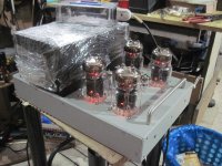
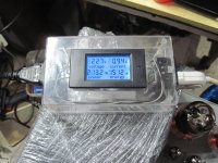
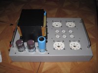
build progress....filaments alone eats 210 watts.....whoa...
Attachments
I think Koonw is right. Try diffrent ef86 till you get what you need (low offset as well as balanced +/- voltage) The ef86 work together with asociated 6c33c. As you can hardly match the 2x6c33c you shal trick them by matching with the asociated ef86. I have allready done this. I suggest also RFT or TESLA NOS ef86 against new russian ones. Also "cooking" at least 24 hours the tubes is a wise step.
any one else tried the russian 6j32? ef86 equivalent...
i got very good results in the other amps that i used that tube in....
any one else tried the russian 6j32? ef86 equivalent...
i got very good results in the other amps that i used that tube in....
I ordered 18 of them on eBay from Russia 5 weeks ago with a view to matching two pairs myself but they have not arrived yet. According to the post tracking website for Russia Post they were going around in circles for 3 weeks within Russia before finally even leaving the country.
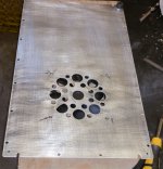
Any photos of the innards? Are you using a cooling fan?build progress....filaments alone eats 210 watts.....whoa...
Congrats. Sounds like you know about care and feeding of 6c33c.Filament burn in successful
No issues!
Regards
David
FYI useful article at Romney the cat. GoodSoundClub - Romy the Cat's Site - The short "6C33C Survival Guide".>
I always burn them in for 3 hrs. Then always heat filament for 10 mins before throwing the switch to B+ power supply. Has resulted in tubes that burn for 2 yrs of daily use without issue.
Any photos of the innards? Are you using a cooling fan?
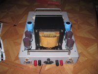
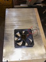
contemplating on cooling fans, i recon 320 watts of power draw once operational..
the traffo i made is rated for 1000 watts and hopefully will run at reasonable temps....
i am using an output coupling cap of 2200 ufd/250 volts in this build...
two reasons, to protect the speakers in the event of tube failure, and to be able to play around
with gnfb if i wanted to...
i am also using rail fuses......
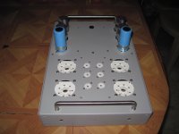
i am designing two boards, one for the psu and housekeeping, and the other for the amp itself...
here the rails are switched in to start the B+ for the amps and uses two relays....
the housekeeping will use a small traffo to energize 3 relays,
power on sequence uses a 3 position rotary switch, off, standby and operate functions....
in the standby function, the front panel led gets to blink once each second and until the filaments
have stabilized to operating current, delay still to be established, then to operate position...
in the operate function, two relays are switched in to start B+....
Attachments

I recommend 4 days and nights in Standby for a 6C33. This can double the life of the tube.
This only applies if B+ has not been applied to the power tube.
Excellent, thanks. I will take your approach on my next set.
contemplating on cooling fans, i recon 320 watts of power draw once operational..
the traffo i made is rated for 1000 watts and hopefully will run at reasonable temps....
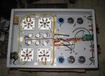
Looks good from underneath. When mine is powered up fully for 2 hours, the chassis gets too hot to touch. A 4 inch wide slim 12 Volt DC computer cooling fan running from one of the 12 Volt heater windings, but half-wave rectified with a 1N4007, brings the temperature down by a full 20 degrees Centigrade. The fan can be so slim - an inch or less - that it can easily fit on the inside of the bottom cover. It also pushes a nice draught of air up the sides of the O/P tubes. It will run at half speed and produce virtually no noise. Well worth considering. BTW, my 3 traffos produce virtually no heat either.
Last edited:
. The fan can be so slim - an inch or less - that it can easily fit on the inside of the bottom cover. It also pushes a nice draught of air up the sides of the O/P tubes. It will run at half speed and produce virtually no noise. Well worth considering. BTW, my 3 traffos produce virtually no heat either.
The fan is actually 120 millimetres square, not 4 inches.
Attachments
Last edited:
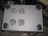
For low wind noise its best to have the exit and inlet with no obstructions
Putting taller feet on the chassis will further reduce fan noise
I will be using a 6" thin low speed Dc fan also at or below 1000 rpm for lowest noise
You can series some 1n4002 diodes to further reduce speed if too fast
Amazing what a little air does to cool things down
Putting taller feet on the chassis will further reduce fan noise
I will be using a 6" thin low speed Dc fan also at or below 1000 rpm for lowest noise
You can series some 1n4002 diodes to further reduce speed if too fast
Amazing what a little air does to cool things down
For low wind noise its best to have the exit and inlet with no obstructions
Putting taller feet on the chassis will further reduce fan noise
I will be using a 6" thin low speed Dc fan also at or below 1000 rpm for lowest noise
You can series some 1n4002 diodes to further reduce speed if too fast
Amazing what a little air does to cool things down
Yes, one large slow-turning fan was my preference. Can't hear it from 4 feet away.
Koonw , you have to be careful modding this ( pp36 ) as the concertina balances the input signal level between the stages. the inverting output of the concertina swings much more then the non-inverting side due to it's connection to speaker output.
When I get some time, I will try a version of this with mosfet concertina and 6922 or 12au7 Super Triode outputs with BJT's.
When I get some time, I will try a version of this with mosfet concertina and 6922 or 12au7 Super Triode outputs with BJT's.
contemplating on cooling fans, i recon 320 watts of power draw once operational..
A fan will really have a big effect on socket life!
- Home
- Amplifiers
- Tubes / Valves
- New Tim Mellows OTL project