Bolserst, I'm curious on the construction of your FR4 panels. Would you mind posting a picture or two? Apologies to alexIG if this is getting too off original topic.
Bondsan, its a good question. Ladder/ lattice structure is another alternative that I've been considering and availability of somewhat affordable fiber glass epoxy laminate makes it more viable for my design. While using HPL would require gluing additional spacers to crossbars to achieve D/S<2.5 which is just too much work I can use relatively thin 0.093-0.125” sheet glass epoxy laminate for spacers/perimeter mounting strips achieving required D/S without additional spacers.
I just use common off the shelf Spray paint primer (only red due to its high talc content and no Titanium Dioxide) and clear acrylic paints.
It is all documented here,
http://www.diyaudio.com/forums/plan...tric-coatings-fact-fiction-2.html#post2893839
I would coat them before attaching them.
jer 🙂
Thank you for the coating recepi. I was thinking about coating rods before gluing to the louver, it would be difficult to maintain uniform thickness. I suppose you would hang them and then spray them from the front and than from back. The back and the front would get thicker coat than the sides. As a result it would affect D/S.
If you give them light wet coats and then flip them and do the other side and let it cure for a bit they will come out pretty even and consistent.
If you do get them a bit to wet it will start to flow, At this point I just keep flipping them until the coating starts to thicken as they cure, Kind of like a Rotisserie.
I had practiced this on a few small short rods for HV testing until I got the hang of how the paint flows, I had meant to show those pictures of the sample rods I did as I was HV testing them but I never got around to it at the time as it was very time consuming as it was.
I used a micrometer to check my coating thickness as I went along.
As I had stated it took only about 8 mil of coating to withstand the the full grunt of my 14kv regulated bias supply (apox. 1500V to 2000V per mil).
After I had found the info I was looking for I went on to make a window screen sample that I used in my original desktop ESL and those are the pictures I had posted.
I do plan on starting a new thread on how I built those with that material and the new coating process sometime.
Not to go OT but my next phase is to build a small Direct drive Class A amp with FET's, That is why I have not started a new set yet.
Running a very high bias increases the efficiency so the amp won't have to have a very high voltage swing in order to produce my goal of +100db-105db at my listening point.
A larger surface area will help this tremendously!!
However, I have already made a small TIG rod style (same size panel as my Desktop ESL's) for such testing when I get to that point.
I have tested the stator's at full tilt bias and amp with transformer and I have had no punch through with them yet.
I have shown those documents several times in other threads so I won't bore you with the pictures.
I did post the simulations in the Segmented ESL thread of my design with 3 or 4 segments and 3.25" wide diaphragm to show the resistor PD requirements at full tilt with test tones.
Another DIYer had made some PCB stators using my coating method and has reported very good results.
I guess that he is to busy enjoying them since they were made and hasn't added anything to his thread about them since then!! He,he,he,he 😀
If you have not seen them, I can search up the links for you if you wish.
I will be getting some new .045" or .035" TIG rod stock for my new set of larger panels as my final thickness was on the order of 85-90 mil with the 1/16" stuff.
My funds at the time had been an issue for me in the last 2-3 years, so that is what had set me back a bit.....But that has been solved now !! 😀
Cheers !!!
jer 🙂
P.S. I do have already made 6 large 10.5" x 36 Stator's 10 years ago but I have not coated them yet and plan to finish those sometime as well.
I guess since that are already made as one large whole Stator I well try making a Segmented Stator for just on the front side of the panel and see how that method works.
It is best to let them cure in a horizontal position.
This way you will have a consistent coating thickness along the length of the rods, If you hang them the coating will flow to one end before it is cured and it will be thicker at the bottom end.
When you lay them down, yes it maybe thicker on one side but that is simply fixed when you re-coat the topside and flip them over to cure.
I was able finish them in 2 or 3 days or so.
The complete build time for my new small test panel was about 1- 1 1/2 weeks for raw materials to finished product.
However the paint take quite some time to fully cure and they are still kind of soft even after the last 3 years since I built them.
But they were fully usable after a few days.
I still get the window screen version test sample out every once in a while to test them them for any microcrack's and have not had any issues yet as the are very flexible and still withhold the voltage of my 14Kv bench supply.
Unlike the issues I had with my original Powder Coated version that I finally burned up after seven years later during my extreme voltage testing.
The powder coating was Awesome at First, But later they formed cracks and leaks and I had to re-coat them with some clear acrylic to get them back where they were when I first made them and then some.
This had a lot to do with using Aluminium as a base material and environmentally abused as well (on purpose), although the did work the First time I fired them up with out even cleaning them after seven years of abuse.
It was the HV testing to see how far they would go that killed them and led me to start working on the coating issues.
But they just weren't designed to do what I had put them through until their final demise.
But for normal use and listening they were more than enough for any type listening and levels up to +105db!!
They were quite loud when I wanted them to be!!! 😉
Amazing for such a small panel that got barely any sound out of them at all when I First powered them up in 2003-4 and got them back out again in 2010 for refurbishing.
I plan on exploring the Powder Coat method again as well.
jer 🙂
Last edited:
I don’t have any pics of the FR4 panels, but the construction is identical to my other phenolic panels that I do have some pics for. The differences were only in thickness and width of the different spacers. In particular, I reduced the width of the inner spacers to minimize loss of radiating area.Bolserst, I'm curious on the construction of your FR4 panels. Would you mind posting a picture or two?
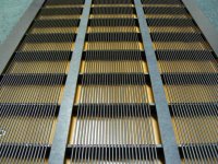
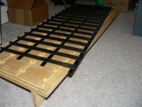
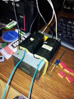
Besides the top and bottom view of the stators I had previously posted elsewhere, I recently located two other pics on an old cell phone. The first one shows a stator frame section after removing from my gluing jig. The jig lets me build stator frame sections up to 36” in length. Then I can glue 2 or more sections together to get whatever height ESL I want. The second shows the glue joint between two stator sections.
For those who haven’t seen them before, I posted other details and polar measurements for one of my ESLs here:
http://www.diyaudio.com/forums/planars-exotics/245454-glue-wire-stators-3.html#post3708397
Exactly. This approach used by Audiostatic, Capaciti, Silberstatic and others really simplifies the construction process.…I can use relatively thin 0.093-0.125” sheet glass epoxy laminate for spacers/perimeter mounting strips achieving required D/S without additional spacers.
By juggling spacer thickness and wire diameter you can get most any D/S spacing you desire.
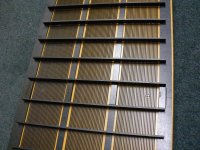
Last pic is an early Silberstatic panel made with clear polycarbonate or acrylic….not sure which.
Attachments


Last edited:
I don’t have any pics of the FR4 panels, but the construction is identical to my other phenolic panels that I do have some pics for. The differences were only in thickness and width of the different spacers. In particular, I reduced the width of the inner spacers to minimize loss of radiating area.
Besides the top and bottom view of the stators I had previously posted elsewhere, I recently located two other pics on an old cell phone. The first one shows a stator frame section after removing from my gluing jig. The jig lets me build stator frame sections up to 36” in length. Then I can glue 2 or more sections together to get whatever height ESL I want. The second shows the glue joint between two stator sections.
For those who haven’t seen them before, I posted other details and polar measurements for one of my ESLs here:
http://www.diyaudio.com/forums/planars-exotics/245454-glue-wire-stators-3.html#post3708397
Exactly. This approach used by Audiostatic, Capaciti, Silberstatic and others really simplifies the construction process.
By juggling spacer thickness and wire diameter you can get most any D/S spacing you desire.
Last pic is an early Silberstatic panel made with clear polycarbonate or acrylic….not sure which.
Thank you for the pics! Indeed a picture is worth a thousand words.
I noticed a couple of things.
Your panels have roughly 50% open area. While there is an opinion that smaller ( 30-35%) open area yields max SPL I thought that smaller open area should result in lower SPL. Dependence of SPL on open area has a bell curve. At 0% open area SPL=0 because all sound radiated by diaphragm is reflected. As open area increases the % of reflected and diffracted sound decreases and SPL increases even though electric field force decreases. Actually ML increased open area in Xstat panels to more that 50% and they claimed that it allowed them to increase SPL. Do you believe that max of the bell curve is around 50%?
It looks like you are gluing diaphragm directly to the stator. According to Capacity it could result in bad CSD and he was suggesting “adding a damping layer at the outer edges of the membrane area to minimize longitudinal resonance modes.” http://www.diyaudio.com/forums/planars-exotics/168069-esls-have-bad-decay-plots.html.
What is your experience?
It is best to let them cure in a horizontal position.
This way you will have a consistent coating thickness along the length of the rods, If you hang them the coating will flow to one end before it is cured and it will be thicker at the bottom end.
When you lay them down, yes it maybe thicker on one side but that is simply fixed when you re-coat the topside and flip them over to cure.
I was able finish them in 2 or 3 days or so.
The complete build time for my new small test panel was about 1- 1 1/2 weeks for raw materials to finished product.
However the paint take quite some time to fully cure and they are still kind of soft even after the last 3 years since I built them.
But they were fully usable after a few days.
I still get the window screen version test sample out every once in a while to test them them for any microcrack's and have not had any issues yet as the are very flexible and still withhold the voltage of my 14Kv bench supply.
Unlike the issues I had with my original Powder Coated version that I finally burned up after seven years later during my extreme voltage testing.
The powder coating was Awesome at First, But later they formed cracks and leaks and I had to re-coat them with some clear acrylic to get them back where they were when I first made them and then some.
This had a lot to do with using Aluminium as a base material and environmentally abused as well (on purpose), although the did work the First time I fired them up with out even cleaning them after seven years of abuse.
It was the HV testing to see how far they would go that killed them and led me to start working on the coating issues.
But they just weren't designed to do what I had put them through until their final demise.
But for normal use and listening they were more than enough for any type listening and levels up to +105db!!
They were quite loud when I wanted them to be!!! 😉
Amazing for such a small panel that got barely any sound out of them at all when I First powered them up in 2003-4 and got them back out again in 2010 for refurbishing.
I plan on exploring the Powder Coat method again as well.
jer 🙂
I do remember now that I tried to spray a coating on a diaphragm that was in a vertical position and and it was not a good idea. 🙂
Do you remember what was the radial variation of the coating thickness?
If you give them light wet coats and then flip them and do the other side and let it cure for a bit they will come out pretty even and consistent.
If you do get them a bit to wet it will start to flow, At this point I just keep flipping them until the coating starts to thicken as they cure, Kind of like a Rotisserie.
I had practiced this on a few small short rods for HV testing until I got the hang of how the paint flows, I had meant to show those pictures of the sample rods I did as I was HV testing them but I never got around to it at the time as it was very time consuming as it was.
I used a micrometer to check my coating thickness as I went along.
As I had stated it took only about 8 mil of coating to withstand the the full grunt of my 14kv regulated bias supply (apox. 1500V to 2000V per mil).
After I had found the info I was looking for I went on to make a window screen sample that I used in my original desktop ESL and those are the pictures I had posted.
I do plan on starting a new thread on how I built those with that material and the new coating process sometime.
Not to go OT but my next phase is to build a small Direct drive Class A amp with FET's, That is why I have not started a new set yet.
Running a very high bias increases the efficiency so the amp won't have to have a very high voltage swing in order to produce my goal of +100db-105db at my listening point.
A larger surface area will help this tremendously!!
However, I have already made a small TIG rod style (same size panel as my Desktop ESL's) for such testing when I get to that point.
I have tested the stator's at full tilt bias and amp with transformer and I have had no punch through with them yet.
I have shown those documents several times in other threads so I won't bore you with the pictures.
I did post the simulations in the Segmented ESL thread of my design with 3 or 4 segments and 3.25" wide diaphragm to show the resistor PD requirements at full tilt with test tones.
Another DIYer had made some PCB stators using my coating method and has reported very good results.
I guess that he is to busy enjoying them since they were made and hasn't added anything to his thread about them since then!! He,he,he,he 😀
If you have not seen them, I can search up the links for you if you wish.
I will be getting some new .045" or .035" TIG rod stock for my new set of larger panels as my final thickness was on the order of 85-90 mil with the 1/16" stuff.
My funds at the time had been an issue for me in the last 2-3 years, so that is what had set me back a bit.....But that has been solved now !! 😀
Cheers !!!
jer 🙂
P.S. I do have already made 6 large 10.5" x 36 Stator's 10 years ago but I have not coated them yet and plan to finish those sometime as well.
I guess since that are already made as one large whole Stator I well try making a Segmented Stator for just on the front side of the panel and see how that method works.
Thank you for the info. I did see your small panels and read your posts.
I always preferred Class A with electrostats when I drove them with SS amps and I hardly knew any difference between A and A/B when I listened to cone speakers. Direct drive class A should sound fantastic with stats but I think it would be very difficult to implement. Have you considered building OTL and using a transformer with a small turn ratio. Something like that Sanders Sound Systems - Build a Hybrid Tube Amplifier to drive Electrostatics (1976)
Bolserst......can you tell us what setup tran you use with your panels....an the best sounding you found..for full rang an above 80hz....thanks
Bolserst,
Very nice looking panels, and measurements! Your stator panel jig is as impressive as your actual panels. Bet that took some time to design and build.
Is your bass equalized, and how far down do you have usable lows?
With your new panels, did you build them with natural or black FR4? I was wondering if I were to use the black FR4 instead of the black ABS that I now use(black from carbon?), would there be enough beneficial dielectric difference to use the natural instead of black?
Thanks
It depends on many factors including comparative size of gaps between wires relative to the D/S spacing. But, it is generally closer to 40%. However it is a broad bell curve, not peaky. So, you can use higher % open area without losing much sensitivity. The benefit to higher % open area is increased acoustic transparency in the top octaves from reduced internal reflections.… Do you believe that max of the bell curve is around 50%?
Some posts on the subject of “optimum” % open area:
http://www.diyaudio.com/forums/planars-exotics/183168-acoustat-answer-man-here-8.html#post2494150
http://www.diyaudio.com/forums/plan...learn-how-build-better-esl-2.html#post2035632
http://www.diyaudio.com/forums/plan...learn-how-build-better-esl-3.html#post2035796
Post on determining sensitivity loss from stator-to-stator capacitance measurement:
http://www.diyaudio.com/forums/planars-exotics/246846-first-time-esl-builder-12.html#post3881204
Yes. Damping of the diaphragm resonances is accomplished with acoustic resistive mesh. (Capaciti did not use this technique). I experimented with damping compounds applied to perimeter and it was very sensitive to application technique, and didn’t work as well as acoustic damping. BTW, the 3M foam tape that is often used by DIY builders for spacer material does not provide much if any damping.It looks like you are gluing diaphragm directly to the stator.
For segmented panels the best transformers I have found are those built using twin bobbins and simple winding technique on UI or C-core. Attached is a pic of the transformer I had wound to drive those panels.Bolserst......can you tell us what setup tran you use with your panels....an the best sounding you found..for full rang an above 80hz....thanks
More details here:
http://www.diyaudio.com/forums/planars-exotics/286989-about-take-esl-plunge-11.html#post4633075
http://www.diyaudio.com/forums/planars-exotics/286989-about-take-esl-plunge-11.html#post4634873
With this winding configuration there is a lot of flexibility to trade off power handling and parastics. Also, the octaves above 20kHz are clean from the multiple resonances often seen in toroidal or EI core transformers.
As mentioned in the post I provided link for, bass is equalized thru segmentation and carefully chosen and damped diaphragm resonance. Response is flat down to about 65-70Hz where it starts rolling off at 18dB/oct, although it sounds clean even at 30Hz.Is your bass equalized, and how far down do you have usable lows?
I used natural FR4.With your new panels, did you build them with natural or black FR4? I was wondering if I were to use the black FR4 instead of the black ABS that I now use(black from carbon?), would there be enough beneficial dielectric difference to use the natural instead of black?
I’m not following your train of thought on benefits from dielectric differences…sorry. 😱
Can you restate the question?
Attachments
Bolserst,
Sorry I was not more clear in my questions. I meant to ask if you use any active equalization for your bass through software, an equalizer, or 'tone controls'. Sounds like you do not need to.
With the FR4: if a person were to build panels just like yours but use welding rod glued directly to the FR4 instead of insulated wire, would it make any difference(insulation wise for the various segments) between the black(probably containing carbon) and the natural. Most likely not, but I was just curious since I'd prefer the black just for the looks. As you can tell, I'm having a difficult time in comprehending the theories of good ESL design.
Again, sorry if this is OT. Any more questions, I'll post in another thread.
It depends on many factors including comparative size of gaps between wires relative to the D/S spacing. But, it is generally closer to 40%. However it is a broad bell curve, not peaky. So, you can use higher % open area without losing much sensitivity. The benefit to higher % open area is increased acoustic transparency in the top octaves from reduced internal reflections.
Some posts on the subject of “optimum” % open area:
http://www.diyaudio.com/forums/planars-exotics/183168-acoustat-answer-man-here-8.html#post2494150
http://www.diyaudio.com/forums/plan...learn-how-build-better-esl-2.html#post2035632
http://www.diyaudio.com/forums/plan...learn-how-build-better-esl-3.html#post2035796
Post on determining sensitivity loss from stator-to-stator capacitance measurement:
http://www.diyaudio.com/forums/planars-exotics/246846-first-time-esl-builder-12.html#post3881204
Thank you. I did not properly expressed my question but you answered the question that I ment to ask.
I should've said optimal SPL while mainatining flat response in HF region. In my books there is no point in SPL when the response is not flat. 50% sounds like a good compromise.
Yes. Damping of the diaphragm resonances is accomplished with acoustic resistive mesh. (Capaciti did not use this technique). I experimented with damping compounds applied to perimeter and it was very sensitive to application technique, and didn’t work as well as acoustic damping. BTW, the 3M foam tape that is often used by DIY builders for spacer material does not provide much if any damping.
I thought that with the mesh you are dumping the fundamental resonance which originates from the air resistance to the diaphragm movement. This resonance has a fundamental frequency F0 and higher harmonics nF0 (n=1.2,3...). An amplitude of harmonics becomes smaller as they increase in frequency. Panels with bad CSD typically exhibit slow transient decay in HF region too which implies that the origin of this effect is different. I wonder if this can be a result of what happens in the ares where the diaphragm is attached to the stators if the tension is not uniform. Another source can be a vibration of the stator itself but then again one wolud think it should be obesrved in LF region.
I like the idea of gluing the diaphragm to the stator. Contact cement will probably work OK with a glass epoxy laminate and it can be relatively easily removed. I agree that about dumping properties of l 3M tapes. All that I tried (both LSE and HSE) hardly provided any dumping at all. They are not cheap especially when it comes to FR.
Hmmmm…that is a good question.… if a person were to build panels just like yours but use welding rod glued directly to the FR4 instead of insulated wire, would it make any difference(insulation wise for the various segments) between the black(probably containing carbon) and the natural. Most likely not, but I was just curious since I'd prefer the black just for the looks...
A few internet searches did not turn up any black FR4 that had electrical properties that differed significantly from natural FR4. Should be just fine.
Are you asking about the general hashy look of CSD plots for most(all?) curved panel ESLs? I seem to recall an old thread that showed a correlation between bad CSD and curved panels. Curve panel ESLs do use extremely high tension in the height direction and next to none in the width direction, so maybe there is something to your thought about non-uniform tension. Perhaps it promotes transverse wave travel in the diaphragm in response to a signal impulse that wouldn’t be damped by acoustic mesh, but would by damped by application of perimeter damping compounds as Capaciti recommended. Perhaps next time I am building some test panels, I'll make an extra with the diaphragm tensioned mainly in just one direction to see what, if any, effect it has on flat panels.…I thought that with the mesh you are dumping the fundamental resonance which originates from the air resistance to the diaphragm movement. This resonance has a fundamental frequency F0 and higher harmonics nF0 (n=1.2,3...). An amplitude of harmonics becomes smaller as they increase in frequency. Panels with bad CSD typically exhibit slow transient decay in HF region too which implies that the origin of this effect is different. I wonder if this can be a result of what happens in the ares where the diaphragm is attached to the stators if the tension is not uniform. Another source can be a vibration of the stator itself but then again one wolud think it should be obesrved in LF region.
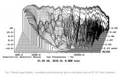
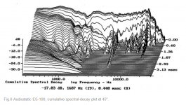
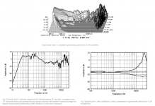
I have not really had any issues with hashy HF CSDs with the flat panels I build. The main concern has been the damping of diaphragm modes in the midrange and lower. Out of curiosity, I just took a look at some of the CSD measurements for flat ESLs published by Stereophile. Not much HF hash to be seen compared to the curved ESL shown in the first attachment…although these flat panels don’t have any mesh damping so the LF modes are still seen.
Attachments
Hmmmm…that is a good question.
A few internet searches did not turn up any black FR4 that had electrical properties that differed significantly from natural FR4. Should be just fine.
Are you asking about the general hashy look of CSD plots for most(all?) curved panel ESLs? I seem to recall an old thread that showed a correlation between bad CSD and curved panels. Curve panel ESLs do use extremely high tension in the height direction and next to none in the width direction, so maybe there is something to your thought about non-uniform tension. Perhaps it promotes transverse wave travel in the diaphragm in response to a signal impulse that wouldn’t be damped by acoustic mesh, but would by damped by application of perimeter damping compounds as Capaciti recommended. Perhaps next time I am building some test panels, I'll make an extra with the diaphragm tensioned mainly in just one direction to see what, if any, effect it has on flat panels.
I have not really had any issues with hashy HF CSDs with the flat panels I build. The main concern has been the damping of diaphragm modes in the midrange and lower. Out of curiosity, I just took a look at some of the CSD measurements for flat ESLs published by Stereophile. Not much HF hash to be seen compared to the curved ESL shown in the first attachment…although these flat panels don’t have any mesh damping so the LF modes are still seen.
I did not pay enough attention to the fact that the majority of published hashy HF CSDs belongs to curved ESLs. I did find in Stereophile some what hashy HF CDS which belong to flat ESLs. They still look better than those of curved ESL
Attachments
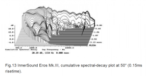
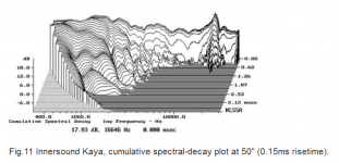
Yup, those still look pretty decent, although I didn't select them for the curved vs flat comparison to keep things on a more apples-to-apples basis.I did find in Stereophile some what hashy HF CDS which belong to flat ESLs. They still look better than those of curved ESL
It is unfortunate that the published CSD for the Soundlab’s used the impulse response with the brilliance control set to maximum. This puts a nearly 25dB peak in the electrical response near 20kHz. The dominate HF ridge in the CSD is due purely to electrical response, not undamped diaphragm resonance.
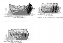
The Quad ESL CSDs rather than being "hashy" have just a few very narrow ridges which I believe are caused by internal reflections between the ESL diaphragm and the two(front & rear) dust cover diaphragms.
Dust Cover Reflections
Dust Cover Pic
Similarly, the Acoustat panels CSDs are not quite as clean as they could be because of reflections from the thick felt pads used for damping the LF diaphragm resonance. The Spectra 1100 also has several 1.5” wide wooden crossbars that go directly across the panels that add to these reflections.
Acoustat Felt Pad damping
(Just noticed, the prominent ridge @ 16kHz in the Acoustat CSD is due to computer monitor according to text)
Attachments
Last edited:
- Status
- Not open for further replies.
- Home
- Loudspeakers
- Planars & Exotics
- Acoustat panels construction