Were the gate stoppers not pretty low in value, and no gate zobel either? Might be worth popping in bigger gate stoppers, say at least 100R.
Good call Jason,
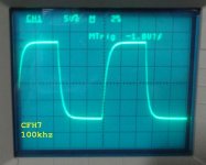
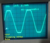
That did the trick. It's playing right now. I have it set to 100mA. BTW, I used 0R33 source resistors.
It sounds good. Very clear with good tight bass. I'm running it on +-39V rails.
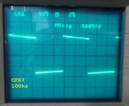
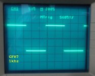
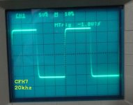
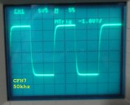
Here are some scope shots.
Attachments

when XRK presented the scheme, I said that the gate resistance is low ....
beautiful waves
Thiago
beautiful waves
Thiago
when XRK presented the scheme, I said that the gate resistance is low ....
beautiful waves
Thiago
You must have just thought it. I don't find a post where you said it. 100R seems to work perfectly.
With a little RC Zobel between the gate and drain (say 150R-100pF) you might be able to go for a lower stopper value. Some experimentation might be required.
I don't recall seeing any of X's images showing phase and gain margin plots. Often in simulation the THD is lowest just before oscillation and in the real world the result ends up being oscillation.
I don't recall seeing any of X's images showing phase and gain margin plots. Often in simulation the THD is lowest just before oscillation and in the real world the result ends up being oscillation.
You must have just thought it. I don't find a post where you said it. 100R seems to work perfectly.
http://www.diyaudio.com/forums/soli...imate-fidelity-amplifier-820.html#post4786071
With a little RC Zobel between the gate and drain (say 150R-100pF) you might be able to go for a lower stopper value. Some experimentation might be required.
I don't recall seeing any of X's images showing phase and gain margin plots. Often in simulation the THD is lowest just before oscillation and in the real world the result ends up being oscillation.
I'm just a builder tester. I suppose it is up to the OP to make changes to his design.
Last edited:
He should ask the moderators to move the discussion from there to here.
I'm just a builder tester. I suppose it is up to the OP to make changes to his design.
Only suggestion based on past experience, not in any way telling the OP what to do. Does give some nice output wave forms with the 100R stoppers though.
Thanks for trying bigger gate stoppers. The sim showed bouncing square waves with 100R. But in reality it's needed to run.
You also stated that T1 and T2 "like" to be C-grades in post 8198.
Where can you find them in C-grades?
Thanks.
Terry,
Thanks for building and debugging it. That's a nice square wave.

I agree, the waves look good. I will try to get it hooked up to my A/B setup in the next day or two. I want to hook it up to a smaller PSU so I can let it play for a while. Right now it is being fed by my variac through a big PSU.
BTW, I used BC546C/556C. The amp is very quiet. It does have a nasty turn on thump. Likely because of all the large caps that have to charge. A speaker protection with delayed on will take care of it.
Interesting about the turn on transient. Being a similar design in general topology to the VSSA / PeeCeeBee I would have expected a silent turn on more like the VSSA / PeeCeeBee and those had some significant capacitance on board as well.
rail 35v attempt BC550c BC560c low noise.
I have plenty of BC550C/560C. Aren't they very similar to the BC546/556 or are they lower in noise?
I thought "C" grades are higher Hfe than the "B" grades?
Just got back from nearly week long trip and find box of PCBs waiting for me. However, they are for AllFET Circlotron amp. 🙂
These boards are still in transit.
These boards are still in transit.
- Home
- Amplifiers
- Solid State
- CFH7 Amp