Impressed 0.075mm approx. hmm quite small.
Smallest milling bit I ever used was 0.5mm, machining one of the fancy engineering plastics (can't remember which one) got some grey hairs that day (machine was running about 60,000 rpm, very very very slow plunge and traverse rate lots of isopropanol based coolant).
Smallest PCB hole I have had to have mechanically drilled was 0.2mm.
Been looking at copper bus bar profiles to reduce skin effect and provide more surface area for cooling, some interesting stuff.
The reason for plunge EDM is that it's a problem getting bits capable of cutting the hardened shafts. Annealing the shaft to drill ruins the other end pivot, and re-hardening after drilling provides the opportunity to distort the staff.
EDM allows cold processing, and then the new hardened pivot wire is pushed in with no interference fit, then he has a jewelry person with a laser welder to weld the pivot in the hole. Final dressing in a jacot on a watchmaker's lathe finishes the job. edit: the weld fillet at the end of the staff is not a problem, as a typical jewelled watch movement has a sapphire surface supporting the tip of the pivot to prevent end shake, so the fillet will never hit the sapphire with the hole in it that supports the pivot. The reason the shoulder does not touch is because the radius of the shoulder against a flat surface increases the frictional losses. In mechanical clocks, this is usually not a problem as motive force is chosen to overcome system losses. In an Atmos or some french clocks, the motive force is limited so this does become important.
John
Last edited:
Instead, I looked upjneutron said:As I said, look up state variable and control theory.
It says "not truly honest or sincere : giving the false appearance of being honest or sincere"jneutron said:disingenuous
If that is what you think then my refusal to argue is fully justified.
Instead, I looked up
It says "not truly honest or sincere : giving the false appearance of being honest or sincere"
If that is what you think then my refusal to argue is fully justified.
It's not a case of you refusing to argue. It is a case of you refusing to understand and discuss.
You've tried several times now to attribute blatently false statements to me. I though better of you, but now wonder about you. Instead of going down the path of learning, you go down the path of attacking.
The physicists here (at work) take less than a minute or two to understand what I have been talking about, so what is confusing me is your complete and utter lack of comprehension. At first, I thought it was how I explained it.
It would appear that is not the reason. I'm beginning to think more and more that it is because I am a mere "EE". I'd like to think that is an incorrect thought. However, your refusal to understand the issue leaves me little else to believe.
John
"Attacking"? "False statements"? I have tried discussing and understanding but with no success.jneutron said:It's not a case of you refusing to argue. It is a case of you refusing to understand and discuss.
You've tried several times now to attribute blatently false statements to me. I though better of you, but now wonder about you. Instead of going down the path of learning, you go down the path of attacking.
Previous experience teaches me that it is difficult to pin you down to exactly what it is that we differ about; I have made at least two extended attempts. All previous attempts by me to clarify the exact point of disagreement were met with various versions of "no, I didn't say that". You say "X"; I say "X" is wrong because ...; you say "I didn't say X, I said Y"; I say "But X is equivalent to Y"; you say " no it isn't and I didn't say Y I said Z and my colleagues here agree with me".
Nevertheless, there are things I say in posts which you object to and there are things you say in posts which I object to. As I cannot determine, despite strenuous efforts, what we disagree about then we cannot resolve the disagreement.
I hope you will forgive me if I attach little importance to second-hand agreement from unknown persons. My issue is not with who you are - I'm not certain I know that, anyway. I have a short memory so even if you told me in the past I would probably have forgotten it. The issue is what you say, but I cannot pin that down so we must leave things as they are. From time to time you will probably wish to object to something I say; from time to time I will probably wish to object to something you say. On other matters we will continue to agree and, hopefully, teach others.The physicists here (at work) take less than a minute or two to understand what I have been talking about, so what is confusing me is your complete and utter lack of comprehension. At first, I thought it was how I explained it.
It would appear that is not the reason. I'm beginning to think more and more that it is because I am a mere "EE". I'd like to think that is an incorrect thought. However, your refusal to understand the issue leaves me little else to believe.
. From time to time you will probably wish to object to something I say; from time to time I will probably wish to object to something you say. On other matters we will continue to agree and, hopefully, teach others.
That is why I said a few posts ago that I enjoy your discourse, even though we disagree on some things.
John
Arguing with a scientist/physicist/engineer is like wrestling a pig in mud. Eventually you realise they are enjoying it 🙂
I believe this definition is the sticking point.
Settling time: The time it takes for a physical system to get from where it was, to where you wish it to be within a specified tolerance.
Within a motion control system, the system response is a result of the strength and speed of the drive and the mass of the object being moved.
If I say "I want you one inch to the left right now!!", the system will not instantly be where I want. Instead, in a well designed system, there will be a move profile from the start point to the end point, and there will be a delay between the command and the finish of motion. That is called the settling time.
Some of the systems I program will take 1 second, some 10 seconds, some even 10 to 100 milliseconds to settle. Voice coil force transducers will settle it's force in low milliseconds, these are consistent with speakers.
A system comprised of a speaker wire can be modeled as either a T-line, or as the equivalent RF LC model. For 20 foot lines running 150 ohms rf driving resistive loads running 4 ohms, the settling time for a step function will be in the ten uSec range. At those time scales, the RF model is sufficient for the task at hand.
As well, the simple LC model will produce the exact same results. I stated this, and Scott also proved this.
Any attempt to claim the RF model is useless for audio frequencies neglects entirely the fact that we are talking about low microsecond responses. Speeds consistent with documented human ITD capabilities.
Now, the other sticking point is, "the signals are too slow, so usec doesn't matter...
First, human ITD sensitivity is that fast.
Second, both models, T-line and lumped element, show precisely this settling time. In fact, if one recalls, lucky provided a lumped model showing exactly the settling time impact on the load voltage a bit back..
Any change at the input to the system will take a certain amount of time until the output of the system has settled into the final value. If the input to the system is a sine, and that sine frequency or amplitude is changed, the output will take the "settling time" until it has achieved the updated information.
This is easy enough to model. When done properly, you will find that any change to the input will cause the output to deviate from the expected value until the system has re-established equilibrium.
To examine this, run an LCR model or a t-line model, set a sine into it, and subtract the output at time t from the output at time t minus 360 degrees. If you abruptly start the sine, you will see the system settle in a specific timeframe. If you change the sine frequency at any point, peak, zero, or on slope, you will see the variance and watch it settle again in the same timeframe.
The system output will NOT track the input with full fidelity whenever the input changed from a consistent signal.
I mention state space theory, as the inductive and capacitive energy at any instant in time are states... At any specific frequency, there is a specific relationship between the storage of energy in the L and C. Use a different frequency, the relationship changes. Change the frequency on the fly, and the energy relationship will NOT change instantly, but requires the settling time before the relationship will be correct for the frequency. In both lumped and t-line modelling, the settling time exists. In t-line, the physical process is visible, in lumped element, it is not as easy to see. Even though, they are equivalent.
John
Sorry for the long post. This I believe is the third time I've explained this. and chances are, it will still not be understood. such is life.
Last edited:
I believe this definition is the sticking point.
Settling time: The time it takes for a physical system to get from where it was, to where you wish it to be within a specified tolerance.
Within a motion control system, the system response is a result of the strength and speed of the drive and the mass of the object being moved.
Yes. Motion control system math is the same as amplifier feedback math, and mechanical systems can be thought of as analogous to electrical systems.
Since all different ways of correctly looking at a system all have to converge on the same physical truth, another way to look at suddenly changing from one frequency to another is to observe that it requires the presence of other frequencies besides the two. That is, if you take a FFT of the abrupt transition from one frequency to another, the abrupt transition will produce or require other frequency components. Essentially you are multiplying the Laplace transform of the new frequency by a step function offset from t=0, for example. (I hope I said that right, but you know what I mean...) And so those new frequencies will interact as they will with the transmission line and load. Eventually, things will settle to a new steady state, within some specified tolerance.
That also assumes there is a meaningful stereo image - so ITD matters? There's a fair amount of modern, non acoustic music, where there is only "false" stereo placement, and it doesn't necessarily affect the result if that is messed with -- though that is very subjective.
For acoustic / orchestral sources, it's a very different matter....
Then again, perception of multiple reflections / RT in concert halls can be very susceptible to "peeking" as I learned from my time working with electro-acoustic mods to listening spaces....
For acoustic / orchestral sources, it's a very different matter....
Then again, perception of multiple reflections / RT in concert halls can be very susceptible to "peeking" as I learned from my time working with electro-acoustic mods to listening spaces....
Yes. Motion control system math is the same as amplifier feedback math, and mechanical systems can be thought of as analogous to electrical systems.
Since all different ways of correctly looking at a system all have to converge on the same physical truth, another way to look at suddenly changing from one frequency to another is to observe that it requires the presence of other frequencies besides the two. That is, if you take a FFT of the abrupt transition from one frequency to another, the abrupt transition will produce or require other frequency components. Essentially you are multiplying the Laplace transform of the new frequency by a step function offset from t=0, for example. (I hope I said that right, but you know what I mean...) And so those new frequencies will interact as they will with the transmission line and load. Eventually, things will settle to a new steady state, within some specified tolerance.
Yes, we agree. And yes, the change does require new frequency components. And, yes, the system will require time to settle to the new state.
I believe the true sticking point is my use of the RF parametrics for the T-line in an "audio" application. That seems to be the red flag in front of the bull (so to speak).
John
That also assumes there is a meaningful stereo image - so ITD matters? There's a fair amount of modern, non acoustic music, where there is only "false" stereo placement, and it doesn't necessarily affect the result if that is messed with -- though that is very subjective.
For acoustic / orchestral sources, it's a very different matter....
Then again, perception of multiple reflections / RT in concert halls can be very susceptible to "peeking" as I learned from my time working with electro-acoustic mods to listening spaces....
What really frosts me is amplitude only panning. Amplitude only location discrimination does not exist in nature. So from the very jump, we are asking our ear/brain combo to interpret something it is not designed to.
Then we top it off with lack of control of the signals across the entire band at ITD levels? Sheesh.
Good think I only listen to the music for the music. I'd be pretty dismayed if I were trying to reconstruct an entire soundfield accurately such that the speakers disappear...
Oh wait, isn't that the goal??
Cheers, John
I believe the true sticking point is my use of the RF parametrics for the T-line in an "audio" application. That seems to be the red flag in front of the bull (so to speak).
Ok, let me try to take it a little further and ask you to explain a little more about what happens in a wire or transmission line as it relates to being consistent with Maxwell's equations. To start more or less at the beginning, Maxwell's equations are homogeneous equations, which means that the solutions to them take the form of an equation, a set of equations, or a class of equations. For a particular problem, depending on boundary conditions we first need to find a particular equation that is consistent with or that satisfies Maxwell. For skin effect, there is an exponential model that is one possible form of solution for Maxwell. There is also a Bessel function that could satisfy Maxwell. A question is which prospective solution to Maxwell is the correct mathematical model for what is happening in a transmission line at audio frequencies. Apparently, what actually happens is not the solution given by the exponential model?
This is two independent entities.Ok, let me try to take it a little further and ask you to explain a little more about what happens in a wire or transmission line as it relates to being consistent with Maxwell's equations. To start more or less at the beginning, Maxwell's equations are homogeneous equations, which means that the solutions to them take the form of an equation, a set of equations, or a class of equations. For a particular problem, depending on boundary conditions we first need to find a particular equation that is consistent with or that satisfies Maxwell. For skin effect, there is an exponential model that is one possible form of solution for Maxwell. There is also a Bessel function that could satisfy Maxwell. A question is which prospective solution to Maxwell is the correct mathematical model for what is happening in a transmission line at audio frequencies. Apparently, what actually happens is not the solution given by the exponential model?
For skin effect, what is usually used is the exponential model. The exponential model is accurate for planar waves impinging on a flat conductive surface, and penetration within.
For wires, the exponential is accurate only when the calculated skin depth is very small compared to the diameter of the wire. That is because there is no real curvature to the system at the depth. If you try to use exponential when the skin depth is the radius of the wire, then you are modelling a system where the wave is converging at the middle, concentrating so to speak. For cylindrical wires, bessels are more appropriate.
The t-line discussion is a whole nuther ball of wax. As you can see, it has a history.
At no time is my use of t-line being considered as defying good ole max...
df has issues with the use of the RF parameters for the t-line. If one goes out a wavelength, then it is correct to also include R into the model, meaning the actual impedance at audio will be much higher. However, within the first 10 to 20 microseconds, there is nothing further to see. If the mismatch were so gross that signals bounced long enough to consider the cable R, then yes, it would be useful to use the higher Z. But after tens to hundreds of reflections, the remaining bounced signal is vanishingly low and below any reasonable settling window.
What is also exceedingly odd, is that my argument is actually enhanced by the introduction of R and the newer cable Z calculated by it's inclusion, so my calculations are indeed a lower limit on what the cable would do.
John
.
df has issues with the use of the RF parameters for the t-line.
By RF parameters, do you mean G and R? If so, they are always there. It's just that sometimes they can be neglected. If the more complete model gives very different answers from the simplified model, then that means the simplified model probably neglects too much for that particular problem. Is that what the argument was about?
By RF parameters, do you mean G and R? If so, they are always there. It's just that sometimes they can be neglected. If the more complete model gives very different answers from the simplified model, then that means the simplified model probably neglects too much for that particular problem. Is that what the argument was about?
Not exactly sure. From what I can see, one primary argument is that the wire is much less than a wavelength so it cannot be considered a t-line. I also believe that the understanding of settling time is lacking, so again the model is erroneously rejected.
John
By RF parameters, do you mean G and R? If so, they are always there. It's just that sometimes they can be neglected. If the more complete model gives very different answers from the simplified model, then that means the simplified model probably neglects too much for that particular problem. Is that what the argument was about?
Unfortunately I lost my files. By RF parameters are meant (to me) L, C, R, and G per unit length. Making the unit length very small and creating a piece-wise model of the speaker cable (200 steps IIRC) you can use an ordinary SPICE analysis to show the convergence of the two ways of looking at it. That is by superimposing the lumped solution (the entire line's L, C, etc.) on the exact solution it is clear they begin to converge on the same energy/time relationship. For a short cable the loses due to R and G usually can be ignored since the power they dissipate is small. There is nothing neglected save radiated power or power lost due to the proximity effect which were never considered in our discussions anyway.
My stance remains R, L, C and G are the only parameters in both approaches.
Last edited:
Not exactly sure. From what I can see, one primary argument is that the wire is much less than a wavelength so it cannot be considered a t-line. I also believe that the understanding of settling time is lacking, so again the model is erroneously rejected.
John
Every wire is a transmission line. It's just that it can often be neglected, just as with any other simplified model. If the more complete model gives a different answer than the simplified model...
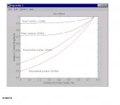
I had a jpeg that described the difference between bessels and exponential, I'll find it..
Edit: here ya go..it's for a 1.5mm diameter wire.
Thanks John
The exact solution predict much less skinning effect than the exponential solution.
I digitized your attached diagram.
I imported the data into Excel.
I drew the diagram there, together with the trend lines (a good fit).
The lines equations maybe of use to analytical minds.
P.S. If you can find some more such diagrams with different wire diameters and/or frequencies, please post them
George
Attachments

- Status
- Not open for further replies.
- Home
- Member Areas
- The Lounge
- John Curl's Blowtorch preamplifier part II