I have good experience with Bourns EM14R0B-M25-L064S optical encoder. It works smooth and does not require debounce except for the push button switch if you use it. In my setup I skip 3 out of 4 steps since I only need 64 steps for my volume controler.
hi, everyone.
hoping to be able to release the software soon; still putting some finishing touches on it.
thread where a lot of the project is discussed and shown:
AMB Laboratories DIY Audio • View topic - TI PGA23xx solid state volume control chip support
some photos on my server:
http://www.netstuff.org/lcduino_pga_build/
the project started with an ebay board as a test platform; I converted the old lcduino code to use this and things were great. then, jeff and I created a custom pcb that offers much more than the cheap ebay board and I adapted the software further for it. the lcd display was left for the old code and the faster led display and rotary encoder was used instead.
photo of one of the builds:

will create a new thread on the diyaudio forum once the documentation is ready and we can begin a public beta test using the custom board (or your own) and the pga chip.
hoping to be able to release the software soon; still putting some finishing touches on it.
thread where a lot of the project is discussed and shown:
AMB Laboratories DIY Audio • View topic - TI PGA23xx solid state volume control chip support
some photos on my server:
http://www.netstuff.org/lcduino_pga_build/
the project started with an ebay board as a test platform; I converted the old lcduino code to use this and things were great. then, jeff and I created a custom pcb that offers much more than the cheap ebay board and I adapted the software further for it. the lcd display was left for the old code and the faster led display and rotary encoder was used instead.
photo of one of the builds:
will create a new thread on the diyaudio forum once the documentation is ready and we can begin a public beta test using the custom board (or your own) and the pga chip.
we've been experimenting with some industrial encoders. They feel a whole lot smoother that the Bourns product, and are readily available.
360RES Rotary Encoder A B 5 24V D38MM | eBay
Smoother in what way?
Is it a push button as well?
Can it
will it do 256 steps in one revolution?
Do i need a debounce circuit for it to work properly?
I have good experience with Bourns EM14R0B-M25-L064S optical encoder. It works smooth and does not require debounce except for the push button switch if you use it. In my setup I skip 3 out of 4 steps since I only need 64 steps for my volume controler.
Hi oleg thanks.
will it make 256 steps in one revolution like you suggested earlier?
I found this one:
ENA1J-B28-L00064L | Bourns 64 Pulse Optical Encoder with a 6.35 mm Round Shaft, Bracket Mount | Bourns
It looks like the one you suggested, but no push putton, i want push button.
hi, everyone.
hoping to be able to release the software soon; still putting some finishing touches on it.
thread where a lot of the project is discussed and shown:
AMB Laboratories DIY Audio • View topic - TI PGA23xx solid state volume control chip support
some photos on my server:
http://www.netstuff.org/lcduino_pga_build/
the project started with an ebay board as a test platform; I converted the old lcduino code to use this and things were great. then, jeff and I created a custom pcb that offers much more than the cheap ebay board and I adapted the software further for it. the lcd display was left for the old code and the faster led display and rotary encoder was used instead.
photo of one of the builds:
will create a new thread on the diyaudio forum once the documentation is ready and we can begin a public beta test using the custom board (or your own) and the pga chip.
Looks amazing!
Hi oleg thanks.
will it make 256 steps in one revolution like you suggested earlier?
I found this one:
ENA1J-B28-L00064L | Bourns 64 Pulse Optical Encoder with a 6.35 mm Round Shaft, Bracket Mount | Bourns
It looks like the one you suggested, but no push putton, i want push button.
Well, it looks similar to the one that I suggested but if you need a momentary switch then it won't do it. The one I suggest has five main advantages: it has a switch which has independent connection from the other circuitry, the A and B channels do not need a debounce to operate smoothly, it has a mounting bracket which can be used to hold the adapter board (see attached), it also has a long shaft which is convenient and it has natural metric dimensions - 6mm shaft diameter and M10x0.75 bushing thread. And yes, it will do 256 steps in one revolution. It took me a while to select the encoder which has all the features which I may ever need. One problem with it and probably other optical encoders from Bourns (but I haven't tried the others) is that the shaft does not have snag fit in the bushing and have noticeable "play" which results in wiggly knob motion if mounted directly on the encoder's shaft. The solution is to use shaft extension and mount the encoder a bit deeper in the enclosure to minimize the knob wiggle when turned. The encoder that I suggest is available from mouser (it is out of stock now but will be back in stock at the end of August). It is also a bit cheaper than the one that you found.
Regards,
Oleg
Attachments

Smoother in what way?
Is it a push button as well?
Can it
will it do 256 steps in one revolution?
Do i need a debounce circuit for it to work properly?
The industrial encoders have ball bearings on the shaft, so they have no slop or friction. They don't have a push button though. The one I sent the link for is 360 steps per revolution.
Cool, thanks oleg 🙂
To make 256 step in one revolution do i need to define something in the code?
I really hope ill manage to fix this poping clicking problem.
Do you work with the PGA2310 and this encoder?
To make 256 step in one revolution do i need to define something in the code?
I really hope ill manage to fix this poping clicking problem.
Do you work with the PGA2310 and this encoder?
The industrial encoders have ball bearings on the shaft, so they have no slop or friction. They don't have a push button though. The one I sent the link for is 360 steps per revolution.
I understand, thank you very much for your suggestion and help.
Ill stick with oleg's recommendetion in addition to you suggested 10uF at inputs, pull up, down resistors.
I use the encoder with the R-2R type volume control, also arduino based. I do not know which code you use but 64 pulse two channel encoders have 256 state changes per revolution. If the code detects them it should work.
you guys should really try this 'motor looking' encoder with bearings.
it has to be tried to be believed. please trust jeff and myself, this is an amazing part and 2 orders of mag. over the crap most people use for rotaries.
don't go more than 360 or 400ppr as the software will start to lose events, even if you do very little in the polling loop. 360 seems to be a perfect res.
I get very close to pot simulation with mine; a full rotation can give me 96db or more! you can divide out the pulses (I have a modulo in my code where I wait until 'n' events are seen before I declare 1 user event) and that's tunable.
no push button on the rotary. you won't want one and won't miss it, either. trust me 😉
buy one for $15, try it and if it sucks, then at least you tried; but you owe it to yourselves to TRY this. everyone I let try my preamp raves about the 'knob feel' and since its opto, its bounce free. you DO need damping or it will freewheel spin. for now, I'm using stick on felt between the knob and the front panel to slow it down and that seems to be an easy and effective way to do it. will be trying other ideas, later, too.
(hint for future: connect a haptic motor to the metal behind the rotary and under cpu control, you can give feedback on things, like if you are about to go over 0 or something like that. can't easily do that with cheap encoders)
in case it was not posted, here is an amazon link for the encoder
https://www.amazon.com/gp/product/B00Y9KDDCY
ebay has them, too.
be careful of the colors on the wires; they are not always the same and the key is printed in chinese (not hard to use google on 'chinese colors' and figure them out, though).
https://www.amazon.com/gp/product/B00Y9KDDCY
ebay has them, too.
be careful of the colors on the wires; they are not always the same and the key is printed in chinese (not hard to use google on 'chinese colors' and figure them out, though).
Thank you linuxworks.
I guess ill oreder both, what you and Oleg suggested.
How do you pnael mount it?
Any Handy pics on how to monut it?
I guess ill oreder both, what you and Oleg suggested.
How do you pnael mount it?
Any Handy pics on how to monut it?
What do you mean, i dont understand.you DO need damping or it will freewheel spin. for now, I'm using stick on felt between the knob and the front panel to slow it down and that seems to be an easy and effective way to do it. will be trying other ideas, later, too.
panel mounting is via 3 screws (m3 thread x 8mm deep, assuming 1/8" plastic front panel, which is my standard). if you search on ebay (if I find it, I'll post) there is a diagram on the hole pattern. its exactly 3 holes around a circle, evenly spaced. I use flat head screws. on amazon, you can find samples if you search on 'axa144' (expensive for those screws, but its what I ended up using).
I'll try to take some pics of my panel without the rotary on it.
the other way (that I think is better, if you have room) is to put the rotary far behind the panel, inside the box, and use old style shaft extenders (like old pots that were mounted near the back panel of the chassis). this way you further decouple the knob from the device.
as for free-wheeling, if you turn the knob, it will spin for many turns on its own. some may like that, but if you have a full 100db of range on a single turn, you won't want to have the volume run up so fast like that on just a 'bump' of the knob.
so, I put felt (cloth with sticky side and fibers on the other side) between the front panel and the knob. that cushions and slows the spin so that it won't spin and spin and spin on its own 😉
felt is not the best material, but its my first try at damping the free-running spin of this motor-like bearing based device.
one pic that I have that gives a hint:
you can see the large center hole and 2 of the screw mount holes I have there. I use a countersink drill to open up the holes so that flat-head screws will fit flush with the surface (or they will block the knob).
I'll try to take some pics of my panel without the rotary on it.
the other way (that I think is better, if you have room) is to put the rotary far behind the panel, inside the box, and use old style shaft extenders (like old pots that were mounted near the back panel of the chassis). this way you further decouple the knob from the device.
as for free-wheeling, if you turn the knob, it will spin for many turns on its own. some may like that, but if you have a full 100db of range on a single turn, you won't want to have the volume run up so fast like that on just a 'bump' of the knob.
so, I put felt (cloth with sticky side and fibers on the other side) between the front panel and the knob. that cushions and slows the spin so that it won't spin and spin and spin on its own 😉
felt is not the best material, but its my first try at damping the free-running spin of this motor-like bearing based device.
one pic that I have that gives a hint:
An externally hosted image should be here but it was not working when we last tested it.
you can see the large center hole and 2 of the screw mount holes I have there. I use a countersink drill to open up the holes so that flat-head screws will fit flush with the surface (or they will block the knob).
ebay ad with hole dimensions:
1 PC New 360P Incremental Rotary Encoder 360P R 6mm Shaft 5 24VDC | eBay
saved file: http://www.netstuff.org/rotary_holes (add .jpg at the end; I didn't want this image to be inlined since its large)
hth
1 PC New 360P Incremental Rotary Encoder 360P R 6mm Shaft 5 24VDC | eBay
saved file: http://www.netstuff.org/rotary_holes (add .jpg at the end; I didn't want this image to be inlined since its large)
hth
Last edited:
pic of the rotary on a panel, showing the rotary behind the panel:
https://www.flickr.com/photos/linux-works/28499131391/in/photostream
https://www.flickr.com/photos/linux-works/28499131391/in/photostream
Hi linuxworks.
Your project is really cool, well planned!
Whats the sceeen size? Is it the 0.96" Oled one?
Your project is really cool, well planned!
Whats the sceeen size? Is it the 0.96" Oled one?
the .96" is the smaller one; mine was the 1.3" one. I have several I bought, since you have to - they change almost every order! vcc and gnd get swapped (I'm serious) and some have a reset and some do not. if you buy any and plan to build a few, get them all at once, test them for what proto they really are and write code to that. sigh. yes, that's how this series is. and the makers still go nuts over the very cheap (and nice looking) oled displays. but its a mess. a real driver and wiring mess, batch to batch.
the i2c ones are mostly standard. the spi ones are my preference since they are way faster. a lot faster. moving bargraphs? you want spi not i2c. static not moving images? i2c is ok. so, know that, going into the project.
the i2c ones are mostly standard. the spi ones are my preference since they are way faster. a lot faster. moving bargraphs? you want spi not i2c. static not moving images? i2c is ok. so, know that, going into the project.
hi guys.
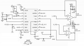
i need some advice using pull up and down resistors.
i found a design over the net but i cant see any where if its verify.
pin1 - ZCEN - to 5V via 10k (in series).
pin2 - SC - pull down 10k
pin3 - SDI - pull down 10k
pin6 - SCLK - pull up 4.7k
pin8 - MUTE - pul down 10k
what do you guys think?
i need some advice using pull up and down resistors.
i found a design over the net but i cant see any where if its verify.
pin1 - ZCEN - to 5V via 10k (in series).
pin2 - SC - pull down 10k
pin3 - SDI - pull down 10k
pin6 - SCLK - pull up 4.7k
pin8 - MUTE - pul down 10k
what do you guys think?
Attachments
- Status
- Not open for further replies.
- Home
- Amplifiers
- Solid State
- Problem controlling a PGA2310