Nice work, Prasi.....
This is the crucial documentation needed for the working production.
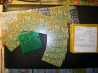
Schemat - BOM - pcb layout
They are all needed and the attention to attention is pivotal to a working amp!
Cheers,
Hugh
This is the crucial documentation needed for the working production.
Schemat - BOM - pcb layout
They are all needed and the attention to attention is pivotal to a working amp!
Cheers,
Hugh
Glad to see guys working for this amplifier.
I will try to polish this farther when i come back.
I will try to polish this farther when i come back.
Nice work, Prasi.....
This is the crucial documentation needed for the working production.
Schemat - BOM - pcb layout
They are all needed and the attention to attention is pivotal to a working amp!
Cheers,
Hugh
Yes sir,
BOM is very important and since my software exports a BOM, I am attaching the same herewith for ease for potential builders as a guide only.It doesnt have retail part nos, but only part nos and values as per schema. It would be great if either you or Ranchu could verify its accuracy.
reg
Prasi
Attachments
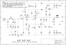
That's it prasi, the schematic is now perfect!
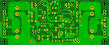
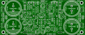
You are a man after my own heart with that board layout. Nice and compact with the output devices underslung, and the power triplet (V+, GND, V-) in close proximity to the output devices.
Lovely work!
You are a man after my own heart with that board layout. Nice and compact with the output devices underslung, and the power triplet (V+, GND, V-) in close proximity to the output devices.
Lovely work!
Any chance that you can change the feedback resistor to a series group with much higher dissipation capability?
1k5 = 2off 750r = 3off 510r = 2off (360r+390r) = 5off 300r
My preference is for 5off 300r, which at 20Vac output (50W into 8ohms), will dissipate 53mW each, rather than 267mW for the single 1k5
1k5 = 2off 750r = 3off 510r = 2off (360r+390r) = 5off 300r
My preference is for 5off 300r, which at 20Vac output (50W into 8ohms), will dissipate 53mW each, rather than 267mW for the single 1k5
Last edited:
Any chance that you can change the feedback resistor to a series group with much higher dissipation capability?
1k5 = 2off 750r = 3off 510r = 2off (360r+390r) = 5off 300r
My preference is for 5off 300r, which at 20Vac output (50W into 8ohms), will dissipate 53mW each, rather than 267mW for the single 1k5
Hi Andrew, Feedback resistor change would entail changing(re-adjusting) of entire layout probably with change in pcb size; may be one can make a string of series resistors and solder the ends in respective pads. would that be acceptable?
reg
prasi
Yes, I changed a couple of amplifier feedback arrangements where the upper leg resistor is a low value.
I prefer series combination because that reduces the voltage applied to each individual resistor as well as reducing the dissipation of that resistor.
Two resistors could be stood up on end and then connect their free ends. Not nice looking, but better than a resistor that changes temperature on every beat/thump!
Alternatively, provide small pads to allow a group of vertical resistors so each resistor has two holes and use the (insulated) long lead into the second hole. Again it does not look as neat when all the other resistors are installed flat.
Unfortunately this is a common failing with layout designers that don't understand the implications of thermal effects on transients.
We might listen at sub 1W average levels but all of us are exposed to transients at least +10dB higher and sometimes +20dB to +30dB higher.
This is a bigger issue with "CFA" style amplifiers, where we see ~1k feedback values instead of 30k in a comparable "VFA".
30times higher dissipation at the same output power.
Feedback Resistor
Hallo Friends.
Nice invoice Andrew, now i understand more what i have seen on Valerys
Tubesumo or likewise board with paralleling FB resistors.
Hi thiagomogi
Wow and very nice we have a Qusi Zilla now.
Wich one you will start a GB now meanman?
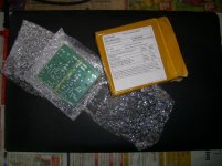
The Prasi boards are received to me today.
I must now check here again, not to forget newest modification- any i have
wrote down to remind.
Eric and Patrick next week i can send you a pair boards.
Send a mail please and it goes on way.
 Bangla.
Hallo Friends.
Nice invoice Andrew, now i understand more what i have seen on Valerys
Tubesumo or likewise board with paralleling FB resistors.
Hi thiagomogi
Wow and very nice we have a Qusi Zilla now.
Wich one you will start a GB now meanman?
The Prasi boards are received to me today.
I must now check here again, not to forget newest modification- any i have
wrote down to remind.
Eric and Patrick next week i can send you a pair boards.
Send a mail please and it goes on way.
Bangla.Attachments
Has anyone built and tested this with C4=2m2F yet?
Does that big feedback capacitor take a long time to charge from switch on?
Where does it charge from, via D3, or via R10, or via R9?
Does it pass the audio signal well?
Does it leak to such an extent that it alters the DC blocking effect?
Does it have an effect on long duration pulses that take excessive time to recover?
Last edited:
Yes, I changed a couple of amplifier feedback arrangements where the upper leg resistor is a low value.
I prefer series combination because that reduces the voltage applied to each individual resistor as well as reducing the dissipation of that resistor.
Two resistors could be stood up on end and then connect their free ends. Not nice looking, but better than a resistor that changes temperature on every beat/thump!
Alternatively, provide small pads to allow a group of vertical resistors so each resistor has two holes and use the (insulated) long lead into the second hole. Again it does not look as neat when all the other resistors are installed flat.
Unfortunately this is a common failing with layout designers that don't understand the implications of thermal effects on transients.
We might listen at sub 1W average levels but all of us are exposed to transients at least +10dB higher and sometimes +20dB to +30dB higher.
This is a bigger issue with "CFA" style amplifiers, where we see ~1k feedback values instead of 30k in a comparable "VFA".
30times higher dissipation at the same output power.
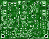
Thats very good info Andrew, I am sure to remember that🙂. So here it goes, ver 4.2 with said vertical resistors for R9 (but I could fit only 2 nos. in the current layout.) Also the BOM is modified to describe this arrangement.
Reg
Prasi
Attachments

Hallo Friends.
Nice invoice Andrew, now i understand more what i have seen on Valerys
Tubesumo or likewise board with paralleling FB resistors.
Hi thiagomogi
Wow and very nice we have a Qusi Zilla now.
Wich one you will start a GB now meanman?
The Prasi boards are received to me today.
I must now check here again, not to forget newest modification- any i have
wrote down to remind.
Eric and Patrick next week i can send you a pair boards.
Send a mail please and it goes on way.
Nice boards BanglaH!good luck on the build.
What is the current consensus listing of component values to be used? So much experimentation had been going on I am at a loss for where the ideal set is?
Hallo Friends.
Nice invoice Andrew, now i understand more what i have seen on Valerys
Tubesumo or likewise board with paralleling FB resistors.
Hi thiagomogi
Wow and very nice we have a Qusi Zilla now.
Wich one you will start a GB now meanman?
The Prasi boards are received to me today.
I must now check here again, not to forget newest modification- any i have
wrote down to remind.
Eric and Patrick next week i can send you a pair boards.
Send a mail please and it goes on way.
nice!... the latest schema is in the previous post (carefully note the component names, they may have changed and some have been added. i.e., Compare schematic on which your PCB is based to the current schematic while populating). All the very best for your build.
(How I wish I was in Germany during October fest!). reg
prasi
I like the Naksa 70 style with the output fets underneath the boardHallo Friends.
Nice invoice Andrew, now i understand more what i have seen on Valerys
Tubesumo or likewise board with paralleling FB resistors.
Hi thiagomogi
Wow and very nice we have a Qusi Zilla now.
Wich one you will start a GB now meanman?
The Prasi boards are received to me today.
I must now check here again, not to forget newest modification- any i have
wrote down to remind.
Eric and Patrick next week i can send you a pair boards.
Send a mail please and it goes on way.
Hi all,
I'm going to build this amplifier on the Thiego PCB as per post #380, because it better suits the case were it will be housed in, and the type of heatsink I can get here in the southest south.
(without any silly component substitution or custom mod for "more power", you know what I mean)
For practical reasons I need the PSU in a separate board as well.
Question is: It's safe to place an order for this PCB to the board house, and still be able to incorporate the latest mods/refinements?
Cheers
J.
The only component added is a cap across R9 which could just be soldered across the resistor legs or added to the underside of the board. All the rest of the changes are just value changes.
The only component added is a cap across R9 which could just be soldered across the resistor legs or added to the underside of the board. All the rest of the changes are just value changes.
Ok , received, I'll go ahead
Congratulations to Ranchu, Thiago and Prasi, and thanks to Terry for testing it out and compared it with others he has in his wide ranging inventory.
Ciao,
Hugh
Ciao,
Hugh
Attachments
- Home
- Amplifiers
- Solid State
- Very simple quasi complimentary MOSFET amplifier