Be careful doing square wave testing as at high amplitudes you are likely to fry transistors if you are not careful! This statement does not just apply to this design but audio amplifiers generally. This is why I suggest running the tests at a safe level of about 2.8Vrms or about 7.8Vpp.
Remember: we don't listen to square waves because they don't exist in music. Its just a useful testing tool to alert to potential problems that aren't apparent looking at a sine signal trace.
Remember: we don't listen to square waves because they don't exist in music. Its just a useful testing tool to alert to potential problems that aren't apparent looking at a sine signal trace.
I know, doing this i want to push this hard so any instability is visible.Be careful doing square wave testing as at high amplitudes you are likely to fry transistors if you are not careful! This statement does not just apply to this design but audio amplifiers generally. This is why I suggest running the tests at a safe level of about 2.8Vrms or about 7.8Vpp.
Remember: we don't listen to square waves because they don't exist in music. Its just a useful testing tool to alert to potential problems that aren't apparent looking at a sine signal trace.
BTW the qwestion is.
Is the amplifier under test a safe-stable amplifier?
Is it any reason to add the compensation capacitor at inverter transistor, or,and the one parallel to feedback resistor?
Yes Ranchu I agree. I would add that these purist tests, along with cheap complementary devices and expensive AP1s in the early seventies, the quasi was relegated as irrelevant. No-one ever highlighted the very good sounding quasi amps, particularly the British (Armstrong, Radford and very significantly the JLH 1969 and 1996.)
Rather than using these square waves in a somewhat unnatural test for an audio amp perhaps we should reflect on why we generally discount our own subjective assessment when many of our technical tests and measurements do not relate well to the subjectives which are derided '...because the are not repeatable or reliable' (to parrot a common notion'.
As quasis go this one is very well designed and even with heavy ringing it would still be stable. As I have stated a couple of times it does not measure well but it sounds very good particularly at voice and lower volumes. This is the SET amp you have without a tube, and BTW a SET measures very, very badly and lots of audiophiles love SETS and they are among the most expensive amps to buy. A friend has just a Chinese 833S SET (125W and 950V on the plate according to their specs but 90W would be more like it) and arguably it was one of the best amps he and I have ever experienced.
Ciao
Hugh
PS: By the way, I made no criticism of Thimios, who uncovered these results doing good engineering! Again, in the attempt to measure everything, designers over many years have tried to describe a power amp but never achieve the essence of audio sound; the topology seems to determine 'how' a sound, while the specs go off on their own unthinking pursuit, giving little indication of the quality of music through human ears.
Last edited:
re posts #612 to #614,
The turn on behaviour of amplifier of this type (ie non-balanced, bootstrap VAS etc) will depend on the charging times of the capacitors C1, C3 and C4 (the ones circled in red).
When the FetZilla amp was being designed, I ran about 100 versions of LTspice to find the optimum value for these capacitors so that the turn on thump was a nice low frequency thump with no sudden transitions...
Hi Paul
I haven't run the simulations (and you must be keen if you did a hundred runs in LTspice) but I think what we'd find that reducing C3 will allow the diff amp to "start up" faster and thus shorten the start up transient. Of course there is a minimum value if the objective is to keep hum and ripple from the input node. I haven't found the switch on impulse to be a problem myself with the specified 47u but I might have a play around and see if cutting it to 10u makes a tangible difference and report back.
Thanks
Christian
Sorry Hugh.🙂Yes Ranchu I agree. I would add that these purist tests, along with cheap complementary devices and expensive AP1s in the early seventies, the quasi was relegated as irrelevant. No-one ever highlighted the very good sounding quasi amps, particularly the British (Armstrong, Radford and very significantly the JLH 1969 and 1996.)
Rather than singly these square waves in a somewhat unnatural test for an audio amp perhaps we should reflect on why we generally discount our own subjective assessment when many of our technical tests and measurements do not relate well to the subjectives which are derided '...because the are not repeatable or reliable' (to parrot a common notion'.
As quasis go this one is very well designed. As I have stated a couple of times it does not measure well but it sounds very good particularly at voice and lower volumes. This is the SET amp without a triode, and BTW a SET measures very, very badly and lots of audiophiles love SETS - a friend has just a Chinese 833S SET and arguably it was one of the best amps he and I have ever experienced.
Ciao
Hugh
Never i say that measurements,right or wrong way,tell the truth about amplifier sound.
I run the test on my risk because i want to know.
Is it necessary the compensation capacitor at the inverter?
Is it stable with 120R for bax resistor?
Is it necessary the 68pf//feedback resistor?
I amn't an amplifier designer,i know nothing about simulation.
I have post results here to take your advanced guides
Nothing else.🙁
Last edited:
Thanks Hugh. I've done all this testing myself, of course, with a 'scope and with expensive speakers, and I haven't had any cause for concern (such as blown tweeters!).
However no amplifier is infallible and I strongly endorse Terry's use of speaker protection.
However no amplifier is infallible and I strongly endorse Terry's use of speaker protection.
Thimios,
I would try a 47pF across the feedback resistor, and I would keep the 120R Bax resistor and probably try 47pF on the inverter transistor too...... My thoughts are that most of the ringing is related to the inverter and the npn output. If you use a complementary output stage it sounds very difficult, BUT, the square wave with reactive load is very, very good. HD
I would try a 47pF across the feedback resistor, and I would keep the 120R Bax resistor and probably try 47pF on the inverter transistor too...... My thoughts are that most of the ringing is related to the inverter and the npn output. If you use a complementary output stage it sounds very difficult, BUT, the square wave with reactive load is very, very good. HD
I don't want good looking scope pictures,i want the sound of this simple quasi comp.but in safe way🙂Thimios,
I would try a 47pF across the feedback resistor, and I would keep the 120R Bax resistor and probably try 47pF on the inverter transistor too...... My thoughts are that most of the ringing is related to the inverter and the npn output. If you use a complementary output stage it sounds very difficult, BUT, the square wave with reactive load is very, very good. HD
I will never try a square wave test again

With my amp, the turn-on sound is more like ffssss than a thump. Not pleasant. I am using 2u2 for the input cap. Not sure if that matters.
The offset jumps around quite a bit with music playing. Nothing big but it moves around.
The offset jumps around quite a bit with music playing. Nothing big but it moves around.
I'm using 2u2 for inp.cap. too.With my amp, the turn-on sound is more like ffssss than a thump. Not pleasant. I am using 2u2 for the input cap. Not sure if that matters.
The offset jumps around quite a bit with music playing. Nothing big but it moves around.
Are you using capacitor at inverter?
Are you using capacitor// to feedback resistor?
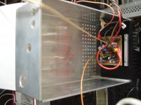
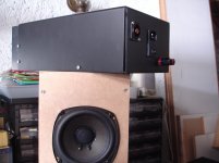
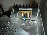
Preparing two cheap monoblocks.
Attachments
Last edited:
Preparing two cheap monoblocks.
Wow!, so you are gonna put them in cabinet, you must be really impressed with this amp then. You may say cheap monoblocks, but looks really impressive🙂.
reg
Prasi
Wow!, so you are gonna put them in cabinet, you must be really impressed with this amp then. You may say cheap monoblocks, but looks really impressive🙂.
reg
Prasi
Thanks Prasi,i will try to finish this.
I'm using 2u2 for inp.cap. too.
Are you using capacitor at inverter?
Are you using capacitor// to feedback resistor?
No, neither of those.
Wow!, so you are gonna put them in cabinet, you must be really impressed with this amp then. You may say cheap monoblocks, but looks really impressive🙂.
reg
Prasi
Thanks Prasi,i will try to finish this.
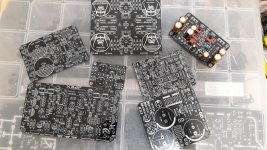
Hi Thiago,i see your layout.Very good Thimios
Regards
Nice work!
If this is your first try ,i can't believe
what you can do in the future.
Last edited:
Hi Thiago,i see your layout.Very good Thimios
Regards
Nice work!
If this is your first try ,i can't belive
what you will do in the future.
Hi Thiago,i see your layout.
Nice work!
If this is your first try ,i can't belive
what you will do in the future.
thank you. one of the first , most already designed some PCB .
Best Regards
- Home
- Amplifiers
- Solid State
- Very simple quasi complimentary MOSFET amplifier