YES, in general forward biased standard LEDs have extremely low noise due to their very low dynamic resistance.
And btw, IR and red LEDs typically have the lowest dynamic resistance (other colors most often have twice the value of red ones)
For non-linearities keep in mind that datasheets almost always show the I-V graphs in a semi-log scale: voltage axis is linear and current axis is log - so the typical hockey stick looks extremely linear if current is shown on a linear scale too!
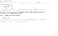
From Wikipedia, this is the diode model:

This is the well known diode equation, that relates I to V in a diode. If you take the voltage derivative of such equation, you will get the conductance of it. And if you get the reciprocal, the diode dynamic resistance. You will see that it is strongly non linear. Then the cathode voltage doesn't respond linearly with anode current creating lots of distortion, like a BJT.
This distorted current to voltage distorted ratio will be amplified by the tube (mu +1) Rl/ (Rl +Ra) appearing in the anode circuit.
I sincerely can't understand why to use a tube amplifier which in turns, will have solid state kinds and amounts of distortion, with the size, cost and power waste of tube amplifiers.
Attachments
Slope resistance is irrelevant -don't worry about it. It is always puny compared with the valve's own internal cathode resistance, so degeneration/distortion will be negligible. Noise due to LED biasing is typically slightly higher (e.g. a couple of dB) than with RC biasing, unless you bypass the LED with a capacitor.
Anyone tried biasing a high gm tube such as a 417a or a triode connected D3a using a LED (or a bypassed LED) in the cathode return (for -1 volt grid bias, 20 ma Ip, etc.)? 417a may be more "challenging"...even with anti-oscillation measures taken...I don't know if it's true in general, but it was true for the specific case of the red and IR LEDs that I measured.
Yes, 417A, 6DJ8, D3A, 6S3P all work just fine with red or Infrared led bias, (depending on bias voltage required) and in fact given the very low resistance values and large electrolytic cap required for RC cathode bias is far more practical, and in the real, not theoretical world performs much better. I have had serious linearity problems with 1000uF electrolytics (Nichicon Muse, and even Blackgates when they were still available) with just a couple of volts across them.
Yes, 417A, 6DJ8, D3A, 6S3P all work just fine with red or Infrared led bias, (depending on bias voltage required) and in fact given the very low resistance values and large electrolytic cap required for RC cathode bias is far more practical, and in the real, not theoretical world performs much better. I have had serious linearity problems with 1000uF electrolytics (Nichicon Muse, and even Blackgates when they were still available) with just a couple of volts across them.
Most common drivers are adequately bypassed for full gain down to 20Hz with 20uf.
I like the idea. Picking a known low noise LED and adjusting the bias voltage with a resistor of low value( to avoid too much NFB and gain reduction). I guess it would be better to put the LED directly on cathode and resistor on ground.
Another option is an LED and resistor string. Its
sort of a half way house between an LED bias and a resistor bias, but opens up a lot more options for the choice of LED.
That's what I usually do: using low value Solen cap (or similar) as a bypass. (In the case I don't like results with LEDs...)
Most common drivers are adequately bypassed for full gain down to 20Hz with 20uf.
Yes, 417A, 6DJ8, D3A, 6S3P all work just fine with red or Infrared led bias, (depending on bias voltage required) and in fact given the very low resistance values and large electrolytic cap required for RC cathode bias is far more practical, and in the real, not theoretical world performs much better. I have had serious linearity problems with 1000uF electrolytics (Nichicon Muse, and even Blackgates when they were still available) with just a couple of volts across them.
A 16V electro will not be completely formed with 2 or 3 volts, from there, the high distortion, and high leaks.
Also, a 100µF i sufficient for a high gain low power stage,a s the resistor in the cathode will have a relatively high ohmic value.
I like the idea. Picking a known low noise LED and adjusting the bias voltage with a resistor of low value( to avoid too much NFB and gain reduction). I guess it would be better to put the LED directly on cathode and resistor on ground.
Yup thats what i did. An LM431 worked better in terms of frequency response, but it was audibly noisy and not as well suited to a preamp stage, and really only useful if you are looking for 2.5volts.
A 16V electro will not be completely formed with 2 or 3 volts, from there, the high distortion, and high leaks.
Also, a 100µF i sufficient for a high gain low power stage,a s the resistor in the cathode will have a relatively high ohmic value.
Partsconnexion have 220uf 4v Black Gates for $2 a piece..
My daily (from 6-7 years) amplifier has cascode DN2540 CCS (12mA) loaded trioded D3a as VAS stage (+ V-Cap coupled FET source follower, DC to 300B SE, 5k:8 OPT).
2V (green) LED bias is atom stable, the sound is natural and crystal clear.
Any R//C bias (I have some handfull of Shinkoh tantalum resistors, Blackgate and Elna Cerafine capacitors, so tried some variations) is degrades the sound.
In my MM phono stage (passive circuit between two stage Raytheon black plate 5751, Tungsram ECC82 CF) I use LED bias (first two stages, 1mA current, green LEDs). I developed and built several phono stages, but it is the best and absolute noisless.
Ericsson LM recommends Rk of 360 ohms for the 417a tube. The time constant of 360 ohms bypassed with 20 uF is high. The 1000 uF bypass value makes more sense. The LED bias sounds worthwhile with 125 v on the anode, 20 ma anode current with -1 volt grid bias. The LED should not require bypassing (hopefully) for low noise amplification...Most common drivers are adequately bypassed for full gain down to 20Hz with 20uf.
Ericsson LM recommends Rk of 360 ohms for the 417a tube. The time constant of 360 ohms bypassed with 20 uF is high. The 1000 uF bypass value makes more sense. The LED bias sounds worthwhile with 125 v on the anode, 20 ma anode current with -1 volt grid bias. The LED should not require bypassing (hopefully) for low noise amplification...
Are you designing a point to point wireless microwave link from your living room to your kitchen for your sound system?
Morgan Jones in his excellent book Valve Amplifiers have some good information about this topic. And as he has shown, a cheap red LED is the best for this application. These have the lowest dynamic resistance of all LEDs. And low dynamic resistance means low noise also, as the noise then will be shunted to ground. No need to search for some extraordinary variants, just go for a generic lowpriced one.
Bypassing affects the LOW frequency cutoff..... want the RC time constant well below lowest useable audio frequencies....hopefully LED bias saves the trouble of the 360 ohm resistor and a 1000 uF capacitor in parallel with it....Are you designing a point to point wireless microwave link from your living room to your kitchen for your sound system?
HLMP Products
Are all HP LEDS. The Opto Electronics Division (OED) was sold off to Avago in 2005. Refer to this link- https://en.wikipedia.org/wiki/Broadcom_Limited
While at HP I sold them by the millions.
Attached are typical forward biased curves for red & green indicater LEDs. Can't remember the particular HP LEDs I used for this back about 15 years ago. 🙂
Attachments
A 16V electro will not be completely formed with 2 or 3 volts, from there, the high distortion, and high leaks.
Also, a 100µF i sufficient for a high gain low power stage,a s the resistor in the cathode will have a relatively high ohmic value.
Try looking at the cathode circuit resistance with a high gm tube (say 25,000 - 50,000 umhos) and a 68 ohm resistor, and you will see why large electrolytics are sometimes used, and why I now use LEDs in this situation.
Try looking at the cathode circuit resistance with a high gm tube (say 25,000 - 50,000 umhos) and a 68 ohm resistor, and you will see why large electrolytics are sometimes used, and why I now use LEDs in this situation.
What types you are referring to? This seems like a discussion now about one-off, rare bird experiments. Radar tubes salvaged... etc.
- Status
- Not open for further replies.
- Home
- Amplifiers
- Tubes / Valves
- 6GF7 and 300B amp