Assuming a good screen, the electric field stops at the screen. Assuming correct connections and truly coaxial construction, the magnetic field outside is zero because the magnetic effects of core and screen currents cancel outside. Hence you don't need to invoke skin effect to get a good coaxial transmission line.Markw4 said:This still assuming the cable as modeled fully defines boundary conditions for wave equations, and that loss of support for propagation is simply a function of, or a definitional point of view regarding, the rate of attenuation.
Skin effect comes in for RF cables, as it means that the screen can support two independent currents - only the inside current takes part in the coax behaviour. The outside current acts like a somewhat thick antenna.
If by "reasonable distances" you mean short distances (after cable propagation speed at audio frequencies has been taken into account) then any cable will do - it is simply a short conductor; no need to invoke transmission line theory.That would still seem to leave the issue of line level 120 ohm cable as workable over reasonable distances, if not for long distance telephony. If so, why then wouldn't paralleled cables work to lower net impedance as some would predict? Or are you saying 120 line level doesn't actually work either without loading coils over even modest distances? How about many 600 ohm cables in parallel?
Paralleling lots of '120ohm' cables gives you a low RF impedance. If RF behaviour is an issue (as it may be for stability with some amplifiers) then you have your lower RF impedance. The audio characteristic impedance will still be nothing like 8ohms. As I said, it will not even be purely resistive. However, paralleling will have reduced cable series resistance and this is the most important issue for a speaker cable. As I said, paralleling may bring benefits but not for the reason some believe.
Okay, then it sounds like you are saying that inductive reactance is so much smaller than resistance that the effects of inductance are negligible and resistance predominates. This still assuming the cable as modeled fully defines boundary conditions for wave equations, and that loss of support for propagation is simply a function of, or a definitional point of view regarding, the rate of attenuation.
That would still seem to leave the issue of line level 120 ohm cable as workable over reasonable distances, if not for long distance telephony. If so, why then wouldn't paralleled cables work to lower net impedance as some would predict? Or are you saying 120 line level doesn't actually work either without loading coils over even modest distances? How about many 600 ohm cables in parallel?
The issues with line impedance for short loudspeaker cables are how they affect the power amplifier's feedback. If you have a discontinuity this can drive many feedback amplifiers to apply correction to the signal at the amplifier end of the cable which is not exactly what is really going on at the loudspeaker end. As even modest amplifiers still have gain at frequencies where the line impedance comes into play this can be an issue. Note that many high end loudspeakers have zobel (constant impedance) networks on the tweeter. That also assists in keeping the behavior from getting nasty.
Now it is certainly possible to design amplifiers that do not suffer from those issues and some are deigned that way.
The problem is to correctly identify what issues are really in play and then address those issues.
Why do you do that?
You got
Z0=sqrt{(R+jwL)/(G+jwC)}
And ask about
Cable is not simply resistor(even resistor is not so simple)...
I can understand fashion in electronic, fashion car, perfumes...
But fashion do not ask for science proof.
We have funny "experimental setup" an "old lions" are joking with it.🙂
Every comment is like "strip tease", showing(explaining) detail by detail, but final picture about this "experimental setup" is "useless setup".
You got
Z0=sqrt{(R+jwL)/(G+jwC)}
And ask about
How about many 600 ohm cables in parallel?
Cable is not simply resistor(even resistor is not so simple)...
I can understand fashion in electronic, fashion car, perfumes...
But fashion do not ask for science proof.
We have funny "experimental setup" an "old lions" are joking with it.🙂
Every comment is like "strip tease", showing(explaining) detail by detail, but final picture about this "experimental setup" is "useless setup".
The problem is to correctly identify what issues are really in play and then address those issues.
OK let's take YOUR picture of your experiment. How does the wire know which end is the source and which end is the 1Meg? Topologically what is the difference in changing the flow of current by reversing the polarity of the source vs reversing the wire and connectors? If you're not careful you might end up disproving superposition.
BTW what is the bias current noise of your massively paralleled op-amps or if you are making a DC measurement how do you account for the fact that it is far larger than your signal?
Now what voltage level do you expect from the voltage drop across a standard interconnect cord fed from 10 millivolts into a 1,000,000 ohm load?
Ed
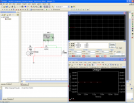
Per your setup drawing and using the most advanced measuring equipment in the most electric noise-free environment ever possible (simulation), I get these numbers (50 Ohm signal source, 3kHz sine, 10mVrms):
Cable resistance //3kHz signal voltage drop across cable ends (Vpp/Vrms/dBV)
1mOhm //28.116pVpp /9.939pVrms /–220dBV
5mOhm // 140.578pVpp/ 49.694pVrms /-206dBV
10mOhm //281.158pVpp / 99.389pVrms /-200dBV
50mOhm //1.405790nVpp/ 496.947pVrms /-186dBV
100mOhm // 2.812nVpp /994.042pVrms /-180dBV
Any and all (if any) of the secondary effect signals to be monitored/observed will be an order or two below that signal level across the interconnect.
10cm piece of interconnect in this setup will pick-up environmental noise some orders of magnitude higher than the 3kHz signal across the interconnect.
The dBV value quoted is to show that even hefty amounts of averaging will not make the FFT picture conclusive except for the case of high resistivity interconnects.
These are ridiculously low signal levels to be measured reliably and repeatably with the best equipment in a typical home/amateur lab environment.
George
Perhaps ES should do an MH and replace the wire with a potato. That would give bigger numbers. Hopefully nobody would spot the difference. It might also make it harder for naysayers to object and wave theory around, as I suspect the electrical properties of common vegetables are not as well known as those for common metals.
If you're not careful you might end up disproving superposition.
[Klingon voice] Naaah... superposition is for the WEAK.
A nasty Ferengi asks what that nV voltmeter with differential input model is, and if its CMMR was considered as an error source. 10mV common mode/1nV differential=140dB
OK let's take YOUR picture of your experiment. How does the wire know which end is the source and which end is the 1Meg? Topologically what is the difference in changing the flow of current by reversing the polarity of the source vs reversing the wire and connectors? If you're not careful you might end up disproving superposition.
BTW what is the bias current noise of your massively paralleled op-amps or if you are making a DC measurement how do you account for the fact that it is far larger than your signal?
First off there is a difference in how the connectors mate in an audio interconnect when you flip the cable around vs what a wire by itself does. I though I had been clear by always referring to an "Interconnect."
At 3,000 hertz the amplifiers should have no problem being AC coupled.
But the actual issue is what the expected result is. From my tests with a sine wave and using Caig De-oxit on the connectors there is no difference!
The first part of this was to demonstrate expectation bias, as the issue in those supposedly correct tests often cited. The other biggie in many tests is the acoustic environment. I used to measure my bedroom at 10 dB "A" weighted, but a visit to the Bruel & Kjaer booth at Infocomm corrected this. That is the limit of the meter. Now when I presented the 10 dBa some folks mentioned that it was not possible to get such a low reading. As usual uniformed opinions from the peanut gallery.
But these tests are clearly all electronic and at what should be clear issues.
Yes I was being nasty about all the folks jumping on the bandwagon of how cables can't be directional and trying to demonstrate that there was a clear bias showing.
Now as you got right the exact experiment is to use a cable under test and connect each end to ground through a 1,000,000 ohm resistor. The you can easily switch the source to either end and see if there is a change.
Now with a simple sine wave I don't expect much and that is simply verification of the setup. However if you use a 1/3 octave noise source centered around 3,000 hertz of less than .01 volts RMS and limit your FFT to say 1,000 to 7,000 hertz and around 32K samples or more and do perhaps 16K averages at the same time as you use your second channel to monitor your noise source you just might see some interesting differences from directivity. You can also turn off you signal source to see the noise baseline. Now what is going on and is it at a level that is perceptable? Don't Know!
Now I think most of the stink is when someone observes something and offers an unsupported or even silly explanation for what is happening. So my first toe dip in the water I think showed that a few folks around here don't really get it. Others are interested and a few might actually try things to compare notes. That is what I think DIY is about.
George,
Sorry I put you to abuse. But I would be curious as to what numbers you get in simulation with no signal source. 🙂 Also it is not the level that I found interesting, it was the FFT shape change just by reversing source and sink. That is actually within a few dB of the total voltage being measured. BTY I was looking at the full interconnect with shield not just a clip of wire. If you want to go a bit more in the real world I do use a non-ferrous enclosure when the levels show outside noise.
ES
Last edited:
[Klingon voice] Naaah... superposition is for the WEAK.
A nasty Ferengi asks what that nV voltmeter with differential input model is, and if its CMMR was considered as an error source. 10mV common mode/1nV differential=140dB
The device under test is isolated from the test instrument. The common mode voltage is effectively zero. Probably not really but certainly small enough coupling that it doesn't show up.
The device under test is isolated from the test instrument. The common mode voltage is effectively zero. Probably not really but certainly small enough coupling that it doesn't show up.
Huh? You answered in Klingon, care to explain? If the output voltage is 10mV then the common mode voltage is 10mV, unless my inner Ferengi alter ego misses something.
Huh? You answered in Klingon, care to explain? If the output voltage is 10mV then the common mode voltage is 10mV, unless my inner Ferengi alter ego misses something.
The source output voltage is 10 mV it is delivered to the load of 1,000,000 ohms by the cable under test. The voltage drop across the cable under test is what is measured. It is around 2nV. As there is no connection between the source or load the only connection is across the wire under test. So any common mode voltage is due to leakage. The source is of course powered by batteries.
Now where do I send you my bill? I think you owe me at least one bar of gold pressed latinum.
Which clearly shows you have no intention of showing anything remotely coherent. Grounding of the entire experimental setup is still a mystery, not to mention the noise picking capability of the entire (apparently floating) setup. Which, the noise, if you also include the capacitive coupling, is also common mode and can actually be much larger than 10mV.
If you did not estimate these error contributions, you are wasting everybody's time, yours included.
When you need a CMRR exceeding -140dB to even approach one significant figure in a meter reading you need to take into account an awful lot of possible signal paths: stray capacitance, stray inductive coupling, electromechanical issues such as piezo effect. Possibly even electrothermal issues. A lot of things to consider and evaluate (N.B. that means calculating numbers).
I know I am not a sufficiently good experimenter to even attempt such a feat. Others on here seem to take a similar view. Sadly, our wisdom is likely to be misinterpreted as cowardice or awkwardness by those who wish to rush in where the wise fear to tread.
I know I am not a sufficiently good experimenter to even attempt such a feat. Others on here seem to take a similar view. Sadly, our wisdom is likely to be misinterpreted as cowardice or awkwardness by those who wish to rush in where the wise fear to tread.
Which clearly shows you have no intention of showing anything remotely coherent. Grounding of the entire experimental setup is still a mystery, not to mention the noise picking capability of the entire (apparently floating) setup. Which, the noise, if you also include the capacitive coupling, is also common mode and can actually be much larger than 10mV.
If you did not estimate these error contributions, you are wasting everybody's time, yours included.
The device under test is easily placed inside a non-ferrous cage and that can be your common reference for your analyzer, if you wish to try it.
The other option is to use a low pass filter on your inputs. There really is not much pickup at 3,000 hertz from a 1M cable.
If you are worried about loop area you can fold your cable under test. This should have no effect if you are not changing it when you switch which side is the input.
On my bench I sometimes see spurs around 13,000 hertz, so I avoid doing measurements where that could interfere.
When you need a CMRR exceeding -140dB to even approach one significant figure in a meter reading you need to take into account an awful lot of possible signal paths: stray capacitance, stray inductive coupling, electromechanical issues such as piezo effect. Possibly even electrothermal issues. A lot of things to consider and evaluate (N.B. that means calculating numbers).
I know I am not a sufficiently good experimenter to even attempt such a feat. Others on here seem to take a similar view. Sadly, our wisdom is likely to be misinterpreted as cowardice or awkwardness by those who wish to rush in where the wise fear to tread.
Why are you repeating someone else's misunderstanding? CMRR is not an issue. At 3,000 hertz you can even use an input transformer if you want to worry about more nonsense.
George,
Sorry I put you to abuse.
Ed, no abuse there.🙂
I use the simulator as the virtual cal lab for any thought experiment, a sanity check if you want.
In the case of your setup, it provides a clear answer for the signal voltages (Ohm’s law gives precise results, no approximate component models involved) with no parasitic elements, unavoidable couplings and extraneous noise injection of a real setup to blur the picture.
But I would be curious as to what numbers you get in simulation with no signal source. 🙂
As expected 😀 with no input signal, the result is a clear zero down to the fV level. (2nd attachment)
That is actually within a few dB of the total voltage being measured. BTY I was looking at the full interconnect with shield not just a clip of wire.. If you want to go a bit more in the real world I do use a non-ferrous enclosure when the levels show outside noise.
My electrical test low-level capability limits are around –110dBV. Add some 30-40dB thanks to FFT and I bottom at around –150dBV.
I can’t reach even the –180dBV level for the 100mOhm interconnect
George
Attachments

George,
Am I confused? 1 uV should be -120 dB re 1 V and that is quite noisy by today's standards! My worst audio band analyzer is 20 nV/rt(Hz.)
But I would be curious to see if you can do it at 1 volt forward and reverse.
Am I confused? 1 uV should be -120 dB re 1 V and that is quite noisy by today's standards! My worst audio band analyzer is 20 nV/rt(Hz.)
But I would be curious to see if you can do it at 1 volt forward and reverse.
Last edited:
The device under test is easily placed inside a non-ferrous cage and that can be your common reference for your analyzer, if you wish to try it.
The other option is to use a low pass filter on your inputs. There really is not much pickup at 3,000 hertz from a 1M cable.
If you are worried about loop area you can fold your cable under test. This should have no effect if you are not changing it when you switch which side is the input.
On my bench I sometimes see spurs around 13,000 hertz, so I avoid doing measurements where that could interfere.
Sorry, unsubstantiated statements. Question is, did you do it yourself? Probably not, since you are unable to show anything consistent.
Sorry, unsubstantiated statements. Question is, did you do it yourself? Probably not, since you are unable to show anything consistent.
I have and other experiments. It wasn't very hard. I am looking to see if anyone else gets the same interesting results.
- Status
- Not open for further replies.
- Home
- Member Areas
- The Lounge
- John Curl's Blowtorch preamplifier part II