It is going to be the single malt, dual rails TarWard amplifier
Hahaha 🙂
Well done. I almost googled that. :ROFL:
If you're going to use TIP31c with no 32's, it has to be quasi comp.
Vaschenko's suggestion is quasi comp but has split supply and direct connect transistors, so ONE BAD SOLDER joint lets go, the experiment toasts your speakers.
I've run an amp so hot the solder melted, before any transistors went. (ST120, *****y heat sinks)
You're building on board right? I build on NEMA CE laminate I drill myself. no printed citcuit means dodgier solder joints.
So an output cap would be a serious speaker saver in many cases. That means single supply. Running e-caps back to back on a speaker output running through zero sounds stupid when the chemical events occur at zero volts.
Those huge heatsinks mean you don't really need a VAS transistor. Double spreader diodes cuts the parts count a lot.
Capacitor output single supply amps mean bigun TGM8, Apex AX6, Armstrong 621, Leak Delta 70, elliott Simple60, 4QD-TEC, Practical Wireless Europa, John Ellis Basic50, Sakis G-amp, nikko TRM210,Panasonic SU380, One already set up for 35 v Power supply was Hifi News January 1980 Simple 30 Watt amplifier.
The earlier listings have lower parts count, IMHO.
I've built AX6 on 3 1/2 x 5 board to drive external NTE60 pair (white box MJ802 I think) to replace my peeling ST120 board. It doesn't like running on a light bulb limiter, keeps latching with the output to speaker cap at 6V DC and lower output transistor full on, on 68 V rail. There may be voltage regulator issues, The dynaco PC15 regulator seemed doomed to latch in protection mode with this AX6 board. My replacement voltage regulator has a 70 v zener and 5 parallel TIP142 darlington pass transistors on a Pentium II CPU heat sink.
Have fun.
Last edited:
If you're going to use TIP31c with no 32's, it has to be quasi comp.
Vaschenko's suggestion is quasi comp but has split supply and direct connect transistors, so ONE BAD SOLDER joint lets go, the experiment toasts your speakers.
I've run an amp so hot the solder melted, before any transistors went. (ST120, *****y heat sinks)
You're building on board right? I build on NEMA CE laminate I drill myself. no printed citcuit means dodgier solder joints.
So an output cap would be a serious speaker saver in many cases. That means single supply. Running e-caps back to back on a speaker output running through zero sounds stupid when the chemical events occur at zero volts.
Those huge heatsinks mean you don't really need a VAS transistor. Double spreader diodes cuts the parts count a lot.
Capacitor output single supply amps mean bigun TGM8, Apex AX6, Armstrong 621, Leak Delta 70, elliott Simple60, 4QD-TEC, Practical Wireless Europa, John Ellis Basic50, Sakis G-amp, nikko TRM210,Panasonic SU380, One already set up for 35 v Power supply was Hifi News January 1980 Simple 30 Watt amplifier.
The earlier listings have lower parts count, IMHO.
I've built AX6 on 3 1/2 x 5 board to drive external NTE60 pair (white box MJ802 I think) to replace my peeling ST120 board. It doesn't like running on a light bulb limiter, keeps latching with the output to speaker cap at 6V DC and lower output transistor full on, on 68 V rail. There may be voltage regulator issues, The dynaco PC15 regulator seemed doomed to latch in protection mode with this AX6 board. My replacement voltage regulator has a 70 v zener and 5 parallel TIP142 darlington pass transistors on a Pentium II CPU heat sink.
Have fun.
Protection board MUST be always in place.
I never ever connect my speakers to anything with no robust protection.
What I'm offering - is a working circuit.
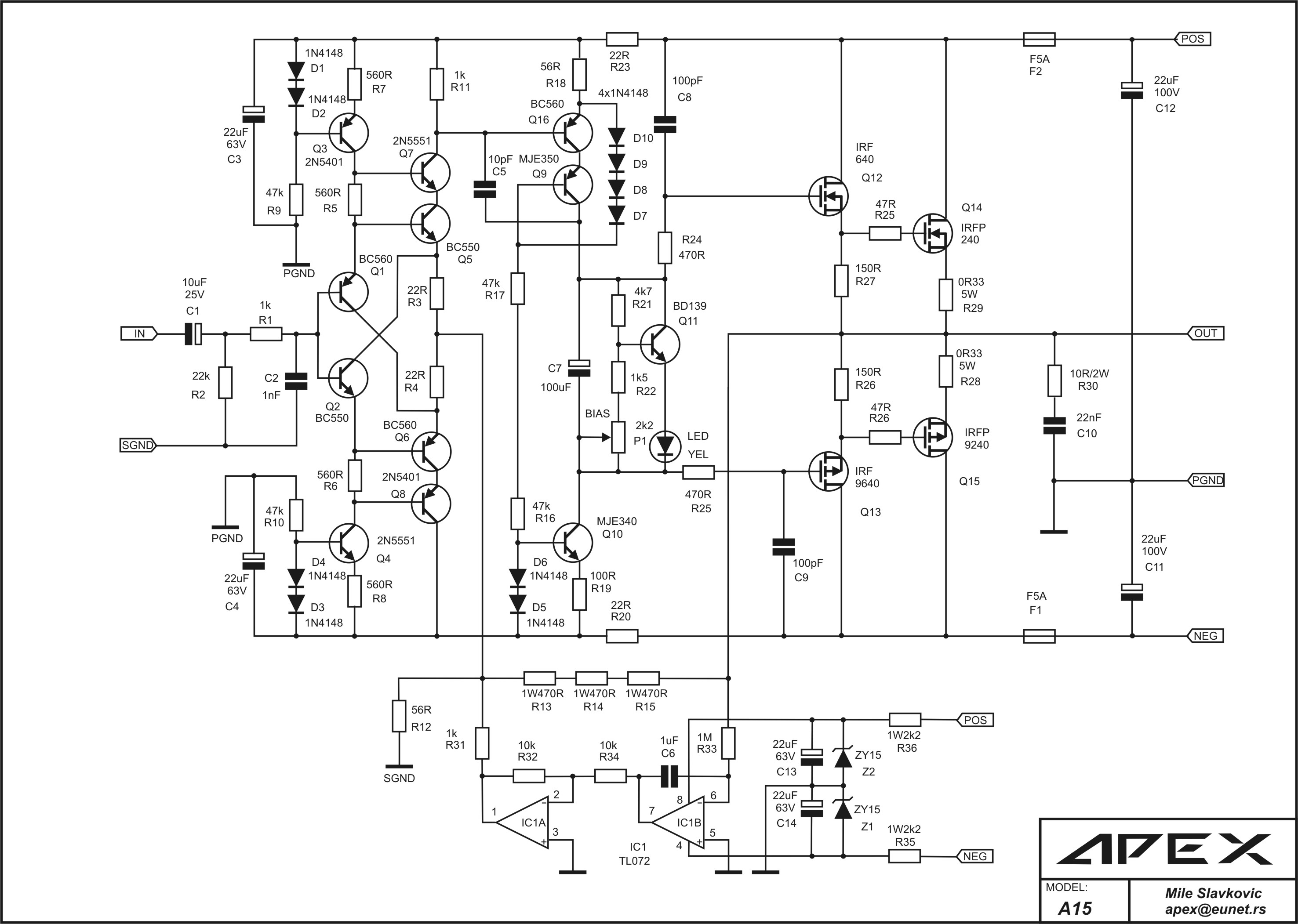
The whole thing to the left from Q4, Q7 is the same as the one used in the many-times-built and well-tested production version of VHex+ amplifier (see the link in my signature).
Very good-sounding one.
The only thing we change - the OPS, as we are looking for a quasi BJT arrangement instead of complementary HexFET one.
Hmm, what about...
Noted on the vhex - fairly complex build though, for a smash it out on the weekend kind of job. That said I'm still tempted...
I'm liking the single supply, output cap idea though. Makes sense for the constraints... and likely level of build precision. I don't see me using output protection on this one.
Attachments
Last edited:
Hmm, what about...
Noted on the vhex - fairly complex build though, for a smash it out on the weekend kind of job. That said I'm still tempted...
ESP products are good, but this one requires adaptation for paralleled TIP31C transistors.
The circuit Vzaichenko has given us is very interesting and I'm temped to build it myself (with different outputs). I also agree that it would be good to start with something simple that can be knocked together in a couple hours.
I've actually built that Rod Elliott P12 design and I can tell you it sounds rather good for such a simple circuit. Its also a great platform for experimentation.... better VAS, better outputs, Baxandall diode on the lower half, better bias generator, etc, etc.
The only caveat is that from memory I had to add a small cap across Q2 base-collector for stability. About 12pF should do it for the other values as specified.
Drop the rail from 70V to 50V and you would get away with a single pair of TIP31C outputs so long as your driving some fairly sensitive and well behaved speakers.
This is what I call a fairly complex build 😛
Then you've clearly never looked too closely at one of the designs from our member, CBS240... 😱
Then you've clearly never looked too closely at one of the designs from our member, CBS240... 😱
Sure, but those ones are "complex", not "fairly complex" 😀
Nevertheless, they work great 😎
And the apex ax6 looks ok to...
🙂 You're talking to a guy who just made a hash of a diamond buffer on protoboard. Simple is better... particularly if I'm to hit my goal of knocking out something in the weekend!
🙂 You're talking to a guy who just made a hash of a diamond buffer on protoboard. Simple is better... particularly if I'm to hit my goal of knocking out something in the weekend!
Last edited:
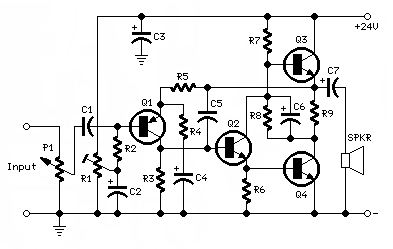
The FH9 I offered is tested and proven to be an easy build (couple of hours) as there are only 7 active parts not including the OPS. I have the vzaichenko VHex+, and indeed it sounds great, but level of complexity is above the FH9 circuit shown here:
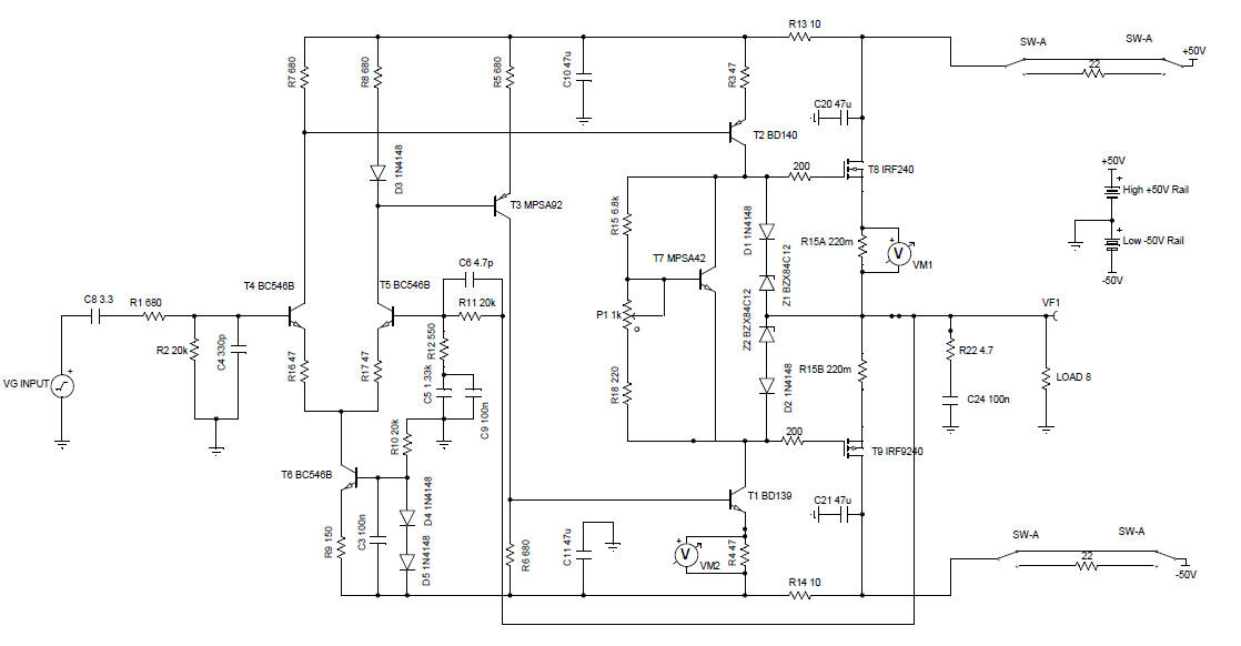
I replaced the MPSA42 with a BD140 or KSC3503 (depending on voltage used).
Again, just because you have a handful of TIP31's doesn't mean that you should use them. You could easily have a handful of IRFP240's and 9240's for under $1ea.
The FH9 works well at 35v to 53v rails - use KSA/KSC drivers and you are covered. Also this simple little amp had been clocked at a bonafide 120w for 15min sine wave drive.
Here's the PCB:
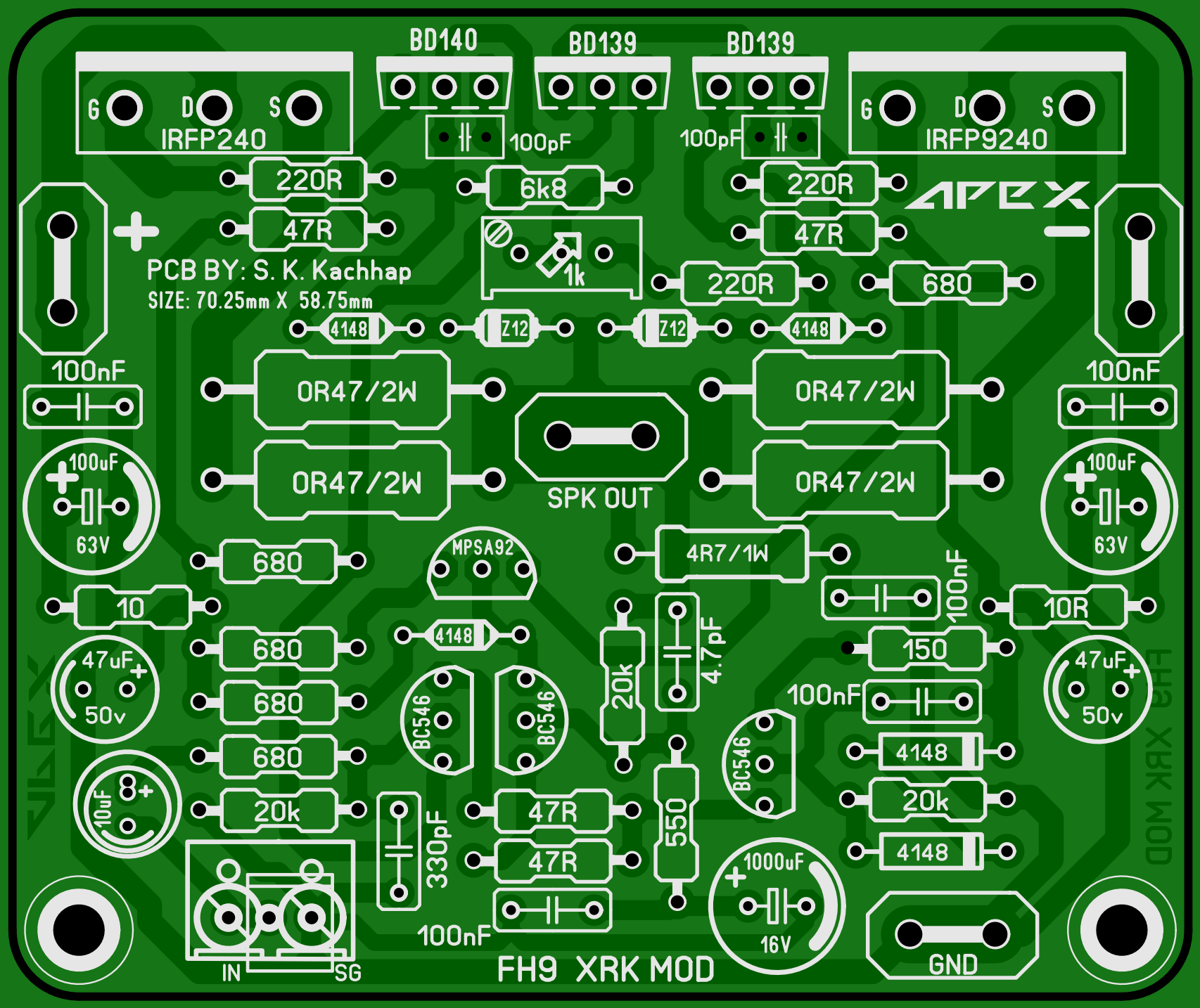
http://www.diyaudio.com/forums/atta...e-fidelity-amplifier-fh9-ver1.04-top-view.pdf
http://www.diyaudio.com/forums/atta...ier-fh9-ver1.04-toner-transfer-silkscreen.pdf
http://www.diyaudio.com/forums/atta...er-fh9-ver1.04-toner-transfer-copper-side.pdf
I replaced the MPSA42 with a BD140 or KSC3503 (depending on voltage used).
Again, just because you have a handful of TIP31's doesn't mean that you should use them. You could easily have a handful of IRFP240's and 9240's for under $1ea.
The FH9 works well at 35v to 53v rails - use KSA/KSC drivers and you are covered. Also this simple little amp had been clocked at a bonafide 120w for 15min sine wave drive.
Here's the PCB:
http://www.diyaudio.com/forums/atta...e-fidelity-amplifier-fh9-ver1.04-top-view.pdf
http://www.diyaudio.com/forums/atta...ier-fh9-ver1.04-toner-transfer-silkscreen.pdf
http://www.diyaudio.com/forums/atta...er-fh9-ver1.04-toner-transfer-copper-side.pdf
V, I've been waiting for you to do a an error correcting MOSFET design & board layout along the lines of Bob Cordell's 1980's paper. I tried a couple years ago but wasn't successful.
This is what I call a fairly complex build 😛
Reading that is hurting my eyes (and brain!). 🙂
Build that P12 this weekend then report back. Its a tweakers paradise.
You won't find simpler that still sounds good, unless its Class A, and who wants one of those, especially someone living in Perth.
You won't find simpler that still sounds good, unless its Class A, and who wants one of those, especially someone living in Perth.
Use two TIP31's to make a Darlington to use as Q4 in this 7w class A single ended circuit that you could indeed knock off on perf board in 1hr.
7 Watt Class-A Audio Amplifier - RED - Page177
7 Watt Class-A Audio Amplifier - RED - Page177
Build that P12 this weekend then report back. Its a tweakers paradise.
You won't find simpler that still sounds good, unless its Class A, and who wants one of those, especially someone living in Perth.
Hey, it was 4deg C here last night! I'd cuddle a class a amp just now.
Actually I was just today considering cranking up the bias on the F5 I built... 🙂
Last edited:
V, I've been waiting for you to do a an error correcting MOSFET design & board layout along the lines of Bob Cordell's 1980's paper. I tried a couple years ago but wasn't successful.
Ranchu, I'm thinking about "transferring" my non-switching OPS experience - works great in BJT setup - to MOSFET environment. You just gave me a kick right now, so I will start doing it very soon - thank you for that 😉
- Status
- Not open for further replies.
- Home
- Amplifiers
- Solid State
- Challenge! Quick and dirty amp build - make a suggestion :)