Not as you suppose
Example for KA = 2pi
JLH mentions two points in this quote..
One of which comes down to cone geometry, which incidentally may give a more shallow cone with the 1:1 compression ratio.
The concept I've drawn here is imperfect, (but so is the HOM performance of certain horns and therefore IMO the concept of the perfect driving wavefront shape for them).. so with a bandwidth based margin of error allowed for, a rule of thumb might be derived eg. the deviation between the longest and shortest distances to the desired wavefront, being essentially the distance from the edge of the dustcap, and how this relates to a wavelength.
Additionally, the magenta tick marks on the cone show the halfway radius where the cone area inside and outside them, looking from the front, are equal. This is to imply the relative contribution strength of the regions.
Example for KA = 2pi
Attachments
![Cone_near_field[1].gif](/community/data/attachments/507/507128-7837baaabc90da06faaf389d5b518966.jpg?hash=eDe6qryQ2g)
Last edited:
Here is why:
WHG
I don't know what kind of explanation this is supposed to be...
For a living I analyze complex business issues and make recomendations of how to go about them. Rule #1 when presenting recommendations is to make a clear recommendation or conclusion stated in plain language, and supported by as much complex analysis as deemed necessary for the case in point. Dropping a bunch of numbers and hoping the audience will figure out what one means never works. And it doesn't seem to work here either.
JLH mentions two points in this quote..
One of which comes down to cone geometry, which incidentally may give a more shallow cone with the 1:1 compression ratio.
The concept I've drawn here is imperfect, (but so is the HOM performance of certain horns and therefore IMO the concept of the perfect driving wavefront shape for them).. so with a bandwidth based margin of error allowed for, a rule of thumb might be derived eg. the deviation between the longest and shortest distances to the desired wavefront, being essentially the distance from the edge of the dustcap, and how this relates to a wavelength.
Additionally, the magenta tick marks on the cone show the halfway radius where the cone area inside and outside them, looking from the front, are equal. This is to imply the relative contribution strength of the regions.
Hey Allen.
Did JLH make that comment in this thread or elsewhere? I ask because I didn't recall reading it.
What I'm understanding from your drawing is the throat should be the same size as the starting point of the horn, which in my case isn't. The throat in my current prototype is 63cm2 and the initial section of the horn is 121cm2. Maybe I should use a larger throat, closer to Sd (94cm2)?
I will need to build a third prototype. But first want to try a couple more things related to the back chamber (impedance tuning and shape).
I will likely go back to a larger mouth. And I am interested in thinking through what size of throat and S1 I should use.
Bogus Issue
"You can do better" is about as concise as it gets. It is up to you to analyze the data provided and determine for your self if it is applicable to all the particulars of your circumstance. The comparison to make is not complex, for it requires only that one know what the differences as well as what the similarities mean in the data presented. For even the casually informed, such evaluation of driver parameters should be self evident, and a 'preaching to the choir' should not be necessary. In any case I remain un-obliged to follow any rules, #1 or otherwise, you choose to make.
WHG
I don't know what kind of explanation this is supposed to be...
"You can do better" is about as concise as it gets. It is up to you to analyze the data provided and determine for your self if it is applicable to all the particulars of your circumstance. The comparison to make is not complex, for it requires only that one know what the differences as well as what the similarities mean in the data presented. For even the casually informed, such evaluation of driver parameters should be self evident, and a 'preaching to the choir' should not be necessary. In any case I remain un-obliged to follow any rules, #1 or otherwise, you choose to make.
WHG
Last edited:
A little confused, I was suggesting a visual approach to expected bandwidth and not much else. Are you suggesting a wavefront will correct itself over distance? or That directivity may become independent of the horn and I didn't model any hom?Example for KA = 2pi
No, I was suggesting the cone could be compared to the desired wavefront, simply to give an estimate of how far out it is at one place vs another. It is illustrative only to the point that the sound will follow various paths in the horn.Hey Allen.
Did JLH make that comment in this thread or elsewhere? I ask because I didn't recall reading it.
What I'm understanding from your drawing is the throat should be the same size as the starting point of the horn,
It was JLH that suggested that the Faital could be retrofitted into an existing horn he had built designed for 8" drivers, and one of the points he noted is that the compression ratio then became 1:1 (IIRC), and that the HF performance was surprisingly good. I wondered at that point why that may be.
I was surprised myself. I'd rather step back at this point and let his comments stand for themselves. Here is the quoted post.
Here is a thread with a horn similar to yours where JLH suggests 1200Hz might be a reasonable expectation in that case.
Last edited:
Answer: I would put the BMS 4599ND compression driver in a very specific kind of waveguide, called an acoustic horn.
Insanity is reserved for those that would put this unit elsewhere, except for testing in a PWT, which incidentally is a waveguide as well.
Rhetorical Question: Why is it that arrogance and stupidity are such good friends, particularly on this website?
WHG
http://www.bmsspeakers.com/fileadmi...ssion_drivers/neodymium/bms_4599nd_curves.jpg
These measurements were done in mystic 2242 horn, and quite big it is, 467x467x467mm, so much lenght and still could give juust a lil bit more boost to low end
BMS 4599ND revisited
Based on the power response of the PFT curve, the very large headroom and equally large sensitivity, I am confident that this driver when paired with a horn of an [Fc] of say 200 Hz, and sized accordingly, could be successfully voiced (drive signal equalized) to operate over the decade of 300-3,000 Hz. in an exemplarily fashion. N.B., at the lower c/o frequency, output requirements will already be down 3-6 dB. If this were a P.A. application, this recommendation, would of course be contraindicated.
WHG
http://www.bmsspeakers.com/fileadmi...ssion_drivers/neodymium/bms_4599nd_curves.jpg
These measurements were done in mystic 2242 horn, and quite big it is, 467x467x467mm, so much lenght and still could give juust a lil bit more boost to low end
Based on the power response of the PFT curve, the very large headroom and equally large sensitivity, I am confident that this driver when paired with a horn of an [Fc] of say 200 Hz, and sized accordingly, could be successfully voiced (drive signal equalized) to operate over the decade of 300-3,000 Hz. in an exemplarily fashion. N.B., at the lower c/o frequency, output requirements will already be down 3-6 dB. If this were a P.A. application, this recommendation, would of course be contraindicated.
WHG
Phase Plug Wavefront Shaping Mission
In the immediate near field, the wave front shape emanating from a cone driver is not particularly ideal for driving a horn. Its shape is frequency dependent as well and also effects the radiation pattern in the fare field.
Use of a properly designed phase plug mitigates this condition as stated in an earlier post. Horn geometry also plays an important role in determining radiation pattern in the far field. Go to Earl Geddes' website for more information on these issues.
Regards
WHG
A little confused, I was suggesting a visual approach to expected bandwidth and not much else. Are you suggesting a wavefront will correct itself over distance? or That directivity may become independent of the horn and I didn't model any hom?
In the immediate near field, the wave front shape emanating from a cone driver is not particularly ideal for driving a horn. Its shape is frequency dependent as well and also effects the radiation pattern in the fare field.
Use of a properly designed phase plug mitigates this condition as stated in an earlier post. Horn geometry also plays an important role in determining radiation pattern in the far field. Go to Earl Geddes' website for more information on these issues.
Regards
WHG
"You can do better" is about as concise as it gets. <snip>
I see. Well, I'll say it again then: I'm not into revisiting my driver choice as of now.
Searching for an ideal could be a never-ending pursuit, and one I'm not interested in. I did that search, you participated (thank you for doing so), I chose a driver. Not onto horn design.
If anything, the new Beyma 6MCF200Nd, with EBP over 560 looks very interesting for horn loading, but I'm not going there now.
So don't take it the wrong way, but in future posts in this thread should you suggest another driver I will assume the post is meant for someone else.
https://martin-audio.com/mla/acousticdesign/midrange-section
martin audio has phase plugged 6,5", that driver looks like phl 1500Nd-SQ, hard to get model but available as martin audio spare
martin audio has phase plugged 6,5", that driver looks like phl 1500Nd-SQ, hard to get model but available as martin audio spare
So be it!
"Saying it again as well": "It is up to you to analyze the data provided and determine for your self if it is applicable to all the particulars of your circumstance." WHG
I see. Well, I'll say it again then: I'm not into revisiting my driver choice as of now.<snip>
"Saying it again as well": "It is up to you to analyze the data provided and determine for your self if it is applicable to all the particulars of your circumstance." WHG
Martin Audio MR Driver/Horn Details
The MLA product uses (2) DLS7005 6-1/2" Drivers, Price £320 each.
They are operated between 320 Hz and 4,000Hz c/o points. [1]
The L8H product uses (2) DLS2536 8" Drivers, Price £291 each.
They are operated between 220 Hz and 2,500 Hz c/o points. [2]
Both units are horn loaded and include "toroidal phase-bungs" in their front cavities. [3].
WHG
References
https://martin-audio.com/mla/acousticdesign/midrange-section
martin audio has phase plugged 6,5", that driver looks like phl 1500Nd-SQ, hard to get model but available as martin audio spare
The MLA product uses (2) DLS7005 6-1/2" Drivers, Price £320 each.
They are operated between 320 Hz and 4,000Hz c/o points. [1]
The L8H product uses (2) DLS2536 8" Drivers, Price £291 each.
They are operated between 220 Hz and 2,500 Hz c/o points. [2]
Both units are horn loaded and include "toroidal phase-bungs" in their front cavities. [3].
WHG
References
Attachments
Last edited:
Dead end
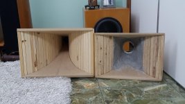
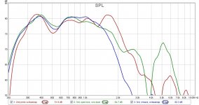
I tried my 3rd prototype: a much longer horn, larger mouth. But it didn't perform nearly as expected. You can see below pictures of the 2nd & 3rd prototypes side by side, and the measured response of both. Clearly I'm not getting the improvements I was shooting for from the increased size. I think I'll drop this path of larger rectangular tractrix horn. Bummer.
So what should I try next? Still keeping the goal of using the Faital M5N12-80 and a passband in the 400/600 to 1800/2000Hz, 104 dB/W efficiency desired.
I'm considering conical horns now, mostly for their directivity properties:
- A conical rectangular, dual expansion horn per Bill Waslo's SynergyCalc spreadsheet, with a 4" throat. This won't play as low, and probably would be low efficiency.
- A 6 or 8-petal conical horn, single expansion.
- Going crazy with a dual expansion conical horn with diffraction slot and phase plug, per Jason Baird & William Webb's patent. Likely too ambitious for me at this point.
Attachments

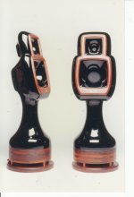
Lewinski I think your starting to see that increasing size doesn't necessarily give you better response. I will try and attach a picture of a three way system with two horns. The upper horn covered 1.6Khz and up with a small pancake driver and the mid horn used a 6 1/2" cone drive that worked from 600hz up to the 1.6Khz upper horn. There is a down firing 8" in that enclosure that took care of all the rest. The mid horn is only about 12" x 12" or so, 1/4 wavelength at 600hz.
Attachments
I tried my 3rd prototype: a much longer horn, larger mouth. But it didn't perform nearly as expected. You can see below pictures of the 2nd & 3rd prototypes side by side, and the measured response of both. Clearly I'm not getting the improvements I was shooting for from the increased size. I think I'll drop this path of larger rectangular tractrix horn. Bummer.
So what should I try next? Still keeping the goal of using the Faital M5N12-80 and a passband in the 400/600 to 1800/2000Hz, 104 dB/W efficiency desired.
I'm considering conical horns now, mostly for their directivity properties:
Open to suggestions!
- A conical rectangular, dual expansion horn per Bill Waslo's SynergyCalc spreadsheet, with a 4" throat. This won't play as low, and probably would be low efficiency.
- A 6 or 8-petal conical horn, single expansion.
- Going crazy with a dual expansion conical horn with diffraction slot and phase plug, per Jason Baird & William Webb's patent. Likely too ambitious for me at this point.
Have you measured the response of said driver on a large flat baffle, outdoors ?
(I ask, because this way you can have a base-line performance reference)
I thought about looking for that plot this morning, Scott, good call. I was thinking of comparing throat details for the two horns.
Lewinski I think your starting to see that increasing size doesn't necessarily give you better response. I will try and attach a picture of a three way system with two horns. The upper horn covered 1.6Khz and up with a small pancake driver and the mid horn used a 6 1/2" cone drive that worked from 600hz up to the 1.6Khz upper horn. There is a down firing 8" in that enclosure that took care of all the rest. The mid horn is only about 12" x 12" or so, 1/4 wavelength at 600hz.
A very unusual design. What is the black material you used?
So the midrange horn is 12"x12" mouth, how long? What profile?
How was the performance of this horn and what were your goals with this design? I mean, likely it was a very good performer, but was it more of a waveguide than a horn? What was the sensitivity of the driver with and without the horn?
There are reasons for this:
1) Any air leaks in the horn, particularly those (in the order of importance) occurring in the compression chamber, horn neck and back chamber will 'kill' performance.
2) Once driver LF limits are reached, it does not matter how much bigger you make the horn. There has to be a strong engine to engage the force multiplier (compression ratio) implemented in the front chamber of the horn.
3) The horn design trade remains, LF loading verses HF pattern control.
For the former, use a Salmon horn with a low [T] value, for the latter use an OS horn with a effective coverage angle. To tweak frequency response at the upper end, use a phase plug.
4) A well designed horn paired with the appropriate driver should deliver a one-decade pass-band. If it does not, the design remains unfinished.
5) Use of diffraction slots will introduce excessive HOM levels into the horn output. This is a good trade for PA venues where crowd coverage in the far field dominates the design priorities. For short-throw, at home applications, such horn design strategies are contraindicated.
Regards,
WHG
I tried my 3rd prototype: a much longer horn, larger mouth. But it didn't perform nearly as expected. You can see below pictures of the 2nd & 3rd prototypes side by side, and the measured response of both. Clearly I'm not getting the improvements I was shooting for from the increased size. I think I'll drop this path of larger rectangular tractrix horn. Bummer.
So what should I try next? Still keeping the goal of using the Faital M5N12-80 and a passband in the 400/600 to 1800/2000Hz, 104 dB/W efficiency desired.
I'm considering conical horns now, mostly for their directivity properties:
Open to suggestions!
- A conical rectangular, dual expansion horn per Bill Waslo's SynergyCalc spreadsheet, with a 4" throat. This won't play as low, and probably would be low efficiency.
- A 6 or 8-petal conical horn, single expansion.
- Going crazy with a dual expansion conical horn with diffraction slot and phase plug, per Jason Baird & William Webb's patent. Likely too ambitious for me at this point.
1) Any air leaks in the horn, particularly those (in the order of importance) occurring in the compression chamber, horn neck and back chamber will 'kill' performance.
2) Once driver LF limits are reached, it does not matter how much bigger you make the horn. There has to be a strong engine to engage the force multiplier (compression ratio) implemented in the front chamber of the horn.
3) The horn design trade remains, LF loading verses HF pattern control.
For the former, use a Salmon horn with a low [T] value, for the latter use an OS horn with a effective coverage angle. To tweak frequency response at the upper end, use a phase plug.
4) A well designed horn paired with the appropriate driver should deliver a one-decade pass-band. If it does not, the design remains unfinished.
5) Use of diffraction slots will introduce excessive HOM levels into the horn output. This is a good trade for PA venues where crowd coverage in the far field dominates the design priorities. For short-throw, at home applications, such horn design strategies are contraindicated.
Regards,
WHG
Last edited:
- Home
- Loudspeakers
- Multi-Way
- Midrange horn design, cone-driven - 201