Hello,
My newly build Pearl 2 is playing music, but some of the measurements are not quite as specified by Wayne. Voltages around Q3 were all wrong so I changed R10 from 10k to 7.5k, now I have Vc=8.3V, Vb=8.1V, Ve=7.4V. I get 0.06V across R21-24 (10R) and 1.92/1.97 across R6 (1.5k). Is that acceptable or should I make some more adjustments? Should R21-24 be increased to 20R?
My newly build Pearl 2 is playing music, but some of the measurements are not quite as specified by Wayne. Voltages around Q3 were all wrong so I changed R10 from 10k to 7.5k, now I have Vc=8.3V, Vb=8.1V, Ve=7.4V. I get 0.06V across R21-24 (10R) and 1.92/1.97 across R6 (1.5k). Is that acceptable or should I make some more adjustments? Should R21-24 be increased to 20R?
As I mentioned in post #676 my Pearl II works. At the time I was not sure about the sound. After leaving it switched on for a few weeks to burn-in I had to disconnect it before I had a chance to listen to it. A few busy months have now passed and I was finally able to hook it up again.
Something is wrong because the sound of my Pearl II is not very good and not at all what I expected. No hum or hiss or any noise or anything like that, just not very refined. More AM than FM, if that analogy makes sense.
I compared the sound of the Pearl II to the lossless digital copy of a vinyl album I had made some years ago using the same TT and cartridge.
- Thorens TD160 with DL110 cartridge --> phono input of Yamaha CX-1000 preamp
- tape output of CX-1000 --> analog input of USB soundcard.
The digital copy sounds much better. Given the pedigree of the Pearl II, that should not be the case.
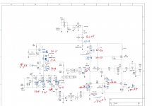
Most of my voltages measured as expected (see attached) but in my Pearl II the voltage drop across R9 is about 3V smaller than in Wayne's example, showing a current of about 14mA, about equal to the total current through R21-24.
Any idea what I should check?
Something is wrong because the sound of my Pearl II is not very good and not at all what I expected. No hum or hiss or any noise or anything like that, just not very refined. More AM than FM, if that analogy makes sense.
I compared the sound of the Pearl II to the lossless digital copy of a vinyl album I had made some years ago using the same TT and cartridge.
- Thorens TD160 with DL110 cartridge --> phono input of Yamaha CX-1000 preamp
- tape output of CX-1000 --> analog input of USB soundcard.
The digital copy sounds much better. Given the pedigree of the Pearl II, that should not be the case.
Most of my voltages measured as expected (see attached) but in my Pearl II the voltage drop across R9 is about 3V smaller than in Wayne's example, showing a current of about 14mA, about equal to the total current through R21-24.
Any idea what I should check?
Attachments
Something is wrong because the sound of my Pearl II is not very good and not at all what I expected. No hum or hiss or any noise or anything like that, just not very refined. More AM than FM, if that analogy makes sense.
Although DL-110 is a high output moving coil cartridge (2.5mV) and might be straining the 2nd (output) stage of the Pearl2 on higher frequency peakish material it could just be that you need to change the loading resistors on the front end from the 47k to 160 ohms.
https://usa.denon.com/us/product/hifi/turntables/dl110
The website info is a bit inscrutable, try experimenting with load resistors before pulling your hair out.
That's a possibility, certainly. Never underestimate loading resistors, and especially in concert with the load capacitance.
I used a DL-110 with my Pearl 2 when I first built it, the Denon being my primary cartridge for most of 2 years. The stock 47K load resistor was used. No load caps were used, the capacitance of the cabling was sufficient. It sounded fantastic.
I used a DL-110 with my Pearl 2 when I first built it, the Denon being my primary cartridge for most of 2 years. The stock 47K load resistor was used. No load caps were used, the capacitance of the cabling was sufficient. It sounded fantastic.
The Denon site does list the electrical impedance of the DL-110 as "160 ohms", but the user manual also lists the recommended load resistance as "more than 47 kOhms", something the Denon site does not do. I am running my DL-110 to my Pearl 2 with 47 kOhms loading with a 100pF (whatever the normal MM loading is) cap in parallel. My interconnect is only 14 " long so it has low capacitance. The sound from my Pearl 2 is fantastic as 6L6 says. Keep trying. Maybe there is overloading, etc. Maybe try your Pearl 2 in a friend's system to isolate the issue, or....
Thanks for the tips. I forgot to mention that I had already lowered the loading resistors by trying different values in R20. It did not solve the problem.
I was hoping someone would spot something obvious in the voltages I measured. It would have been easier to have some idea what the cause would be.🙂
I will try to eliminate problems in the Thorens/Denon combo first. I should have my old Yamaha CX-1000 preamp in storage somewhere. I will try to find it so I can check that the Thorens/Denon combo are not causing the problem!
Hi aoc,AlbertNL I couldn't decipher voltage values across R21-24
The measured values (in mV) are:
- 35.1 36.9 35.1 and 35.1 for right channel (blue)
- 33.6 34.1 34.9 and 34.4 for left channel (red)
Last edited:
Is Q2 (ZVP3310) supposed to get quite hot or is it something wrong with my Pearl? I measured about 13mA going through Q2. Voltage drop on my LED is 1.9V.
New Pearl builder
Hi All. I am waiting for my Pearl boards to arrive. In the meantime, I am slowly readin through this thread from page 1 ( by now gotten to p. 15). My conclusion so far is that 6L6 is without any doubt the most patient and pedagogical person on this earth. He/she is amazing and I hope tgat I can also get his/her help if nescessary.
Cheers.
Grunnet
I am now (very) slowly filling my boards and just wnt to make sure that I have understood the issues of cartridge loading and gain correctly.
In the place of R14 and R20 I have mounted sockets to facilitate changes for different cartridges.
For all cartridges it is normally a good odea to follow manufacturers recommandations, so check these.
For the great majority of MM cartridges, I would leave R20 empty and fill R14 with a 1 kOhm resistor. Thus loading the cartridge with 47kOhm and having a 55db gain. Right?
( the capacitive loading is given by C22 and set at 100pF, which is pretty much standard for MM cartridges)
For typical MC cartridges, I would fill the socket at R20 with a 100 Ohm resistor and the socket at R14 with a 300 Ohm resistor, resulting in a cartridge load of some 100 Ohm and a gain of 65 db. (Capacitive loading of MC cartridges are inconsequential).
Is this all correctly understood?
Is this all correctly understood?
Yes.
What are these resistor sockets you speak of?
I bought the sockets at Mouser ( part #506-510-AG90D). The principle is similar to opamp sockets. If it works, you should be able to change settings form f.ex. MM to MC without soldering, i.e. without removing the PCBs from the cabinet.
Umbilical cable? I have been reading all over diyaudio to find a clear answer to this one, to no avail. Should the umbilical cable be screened or not? Is it advisable or is it necessary? One problem is that I have some 3 pin xlr connectors, that I would like to use - a screen would use 4 pin connectors. Another problen is that if I need screened cabling, I would have to opt for relatively thin gauge microphone cable or the like - not ideal for DC transmission. So it is a dilemma. My gut feeling is to go for unscreened 3 lead, 1 mm power cable and see how it goes. Any advice?
Umbilical cable? I have been reading all over diyaudio to find a clear answer to this one, to no avail. Should the umbilical cable be screened or not? Is it advisable or is it necessary? One problem is that I have some 3 pin xlr connectors, that I would like to use - a screen would use 4 pin connectors. Another problen is that if I need screened cabling, I would have to opt for relatively thin gauge microphone cable or the like - not ideal for DC transmission. So it is a dilemma. My gut feeling is to go for unscreened 3 lead, 1 mm power cable and see how it goes. Any advice?
I don't think screened cable is required here. I used a standard XLR cable (screened) with 4 pin connectors (just to avoid any mistakes with signal 3 pin XLRs on my Aleph J).
Thanks forour replies. Right or wrong, I am a little worried about the typical wire gauge (24, .2 mm2)in standard xlr cable. The Kimber-style braid combined with a mesh screen sounds more like my style, belt AND suspenders. Thebraid and the screen guards against RF nouse and a homemade braid allows for a thicker gauge (17-18, .74-1 mm2), which should help DC transfer. The smaller gauge wire may be ok for a 1 meter cable and the amperes needed, but I am not sure.
I bought the sockets at Mouser ( part #506-510-AG90D). The principle is similar to opamp sockets. If it works, you should be able to change settings form f.ex. MM to MC without soldering, i.e. without removing the PCBs from the cabinet.
I don't quite get it. That part number shows 10 positions, are you cutting them to fit on the pcb? Can you post pics to show this implementation?
I cant do a picture, but you may find one elsewhere in this thread. You have found the right thing at Mouser. You simply cut one from the strip and solder that pin onto your board. After that you can insert a resistor into pins instead of soldering the resistor into the board. Smart, methinketh.
Avoiding MM overload
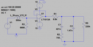
Here's a thought, borrowed unabashedly from Bob Cordell's "VinylTrak" preamplifier -- the T5 compensation is accomplished using the inductance of the moving magnet cartridge's inductance, in this case 500mH, loading it with a resistor other than 47k. As T5=75uS, set the compensating resistor at T5=L/R, or ~6.6k. This means that the HF energy is attenuated before going into the first gain stage.
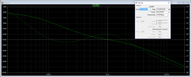
For the second passive network, after the K170 first gain stage, the math is now fudged such that T5 is now 1uS. Knowing that R1*C2=T3*T5/T4 you get the following values, I plugged an opamp as a buffer between the stages for simplification, and the following results.
Here's a thought, borrowed unabashedly from Bob Cordell's "VinylTrak" preamplifier -- the T5 compensation is accomplished using the inductance of the moving magnet cartridge's inductance, in this case 500mH, loading it with a resistor other than 47k. As T5=75uS, set the compensating resistor at T5=L/R, or ~6.6k. This means that the HF energy is attenuated before going into the first gain stage.
For the second passive network, after the K170 first gain stage, the math is now fudged such that T5 is now 1uS. Knowing that R1*C2=T3*T5/T4 you get the following values, I plugged an opamp as a buffer between the stages for simplification, and the following results.
Attachments
- Home
- Amplifiers
- Pass Labs
- Building a Pearl 2