Started off the day with a little drama. First time to build something with a PS. Not so successful yet. Initially had the primaries wired incorrectly in the wiring block (neutral to red/black primary, hot to red/black primary). No LEDs on the PS and eventually I figured it out (after being saved by some fuses).
I powered up after correcting (I hope) my first blunder. When I powered it up the LEDs lit and so did the bleeder resistors. For some reason I used 4.7 ohm instead of the 2.2 ohm. They both smoked....quickly.
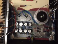
Is this the only problem you see?? Did I hose the PS supply board up when I screwed up the transformer primaries. I initially shorted the AC and tripped both fuses in an effort to "fix" the AC to transformer folly. Do you guys see anything blaring? I did not electrically isolate the bridge rectifiers with Keratherm.
Even with the pre 4th fireworks, this is fun. we'll see if I can avoid killing myself.
Thanks for any much needed assistance,
Jeff
I powered up after correcting (I hope) my first blunder. When I powered it up the LEDs lit and so did the bleeder resistors. For some reason I used 4.7 ohm instead of the 2.2 ohm. They both smoked....quickly.
Is this the only problem you see?? Did I hose the PS supply board up when I screwed up the transformer primaries. I initially shorted the AC and tripped both fuses in an effort to "fix" the AC to transformer folly. Do you guys see anything blaring? I did not electrically isolate the bridge rectifiers with Keratherm.
Even with the pre 4th fireworks, this is fun. we'll see if I can avoid killing myself.
Thanks for any much needed assistance,
Jeff
Attachments
Just where is this bleeder resistor? Normally the term implies a resistor across the terminals of a power supply bypass cap.
If those capacitors saw a reverse bias voltage while the fuse was being
blown the first time around, you may have damage there, and they might
be drawing a lot of current.
Normally what I call a bleeder resistor is a high value resistor across the
power supply which slowly bleeds off the charge when the AC power is
removed so that you don't come along later and get surprised by still-charged
capacitors. Value for that will be several Kohms. If you are using 2.2 ohms
for that, it will smoke.
😎
No k here. I put a 4.7 ohm instead of a 2.2k ohm. I suspect that's the issue. Do you think I cooked anything else or can I just replace with the correct resistance?
No bulb tester. Was waiting to use that when the amp board were attached. Looks like that might be the 3rd (or 4th) learning opportunity. I suspect the more they cost, the better I might remember.
Is there a simple way to test the caps after I replace the smoked resistors and put together the bulb tester?
Is there a simple way to test the caps after I replace the smoked resistors and put together the bulb tester?
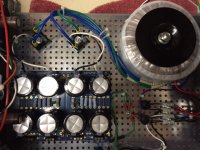
Here is a little better pic.
Your toroid transformer and psu pcb inside of the chassis are in strange position.
Why you don't try reproduce the same elements position structure like in all excellent build guides made by 6L6
or see on First Watt inside amplifier photos ?
They protect your input Jensen transformers from magnetic field made by psu toroid
and audio inputs & outputs are in better position to be far away in opposite direction to psu again.
Have fun 🙂

ps something like that :
http://www.diyaudio.com/forums/pass-labs/277850-f6-illustrated-build-guide.html
Last edited:
Positioned that way because I didn't have a L bracket to mount the toroidal in a 300mm deep case. Guess I can order (or make) one as a Digi-key order appears to be in the near future.
Trying to get an idea if I should go ahead and get new caps to avoid additional postage later. The caps I used are 35v. I guess that wouldn't help me much with the potential current spike Nelson alluded to. I have 2 extra caps (and a couple of 25V 15000uf caps). Would you guys recommend sucking it up and replacing the caps or trying to see what follows?
One additional question. Do folks use Keratherm under the rectifiers?
Thanks for all your help.
Jeff
If the caps are installed the right way around - which after comparing your arrangement to the silkscreen of the boards as shown in the diyaudiostore seems to be the case - they should be fine. The culprit here is the 4R7 "bleeder" resistor, which practically formed short across the psu's output. Replace them both with resistors of proper value.
And you can find usable L-brackets at almost any hardware store.
And you can find usable L-brackets at almost any hardware store.
RodeoDave,
I think Nelson was saying my caps may be toast because I screwed up the primary winding on the transformer and may have sent a bunch of current through the board before the fuses blew. This is over my head (clearly) but sounds bad🙂 If it were a single issue of the wrong resistor the caps would be dandy??
Kevin are you saying I still have the primaries incorrect? The inrush suppressors are the CL60s? I think I have it right at the input side of the block. Maybe I have mixed the primary pairs at the output side of the block?
Sorry to be so clueless/needy.
If the fuse blew very quickly then the capacitors may have survived.
Do you have a lightbulb tester to help establish if there is any excess current draw from potentially damaged capacitors?
Then you would have an indication if something is wrong, and it appears good maybe progress carefully, measuring for any excess heat anywhere.
I recently did something very similar, and the capacitors survived, they had some tremendous specs for amperage/ripple, and that may be what saved them.
You could also measure for ripple after everything comes out good, just for peace of mind.
Your cazapatators are probably fine the wrong value bleeder resistor would have saved them. When you have it hooked up correctly through a light bulb tester you should see the light bulb glow brightly at first and then go to a dim glow. Measure the voltage across the capacitors then. Leave them hooked up for 4 days and then check the voltage again. That should reform any damage. Most capacitors can take a bit of a joke. But if for example you get the voltage backwards they can explode and it is not with laughter.
As long as you didn't reverse the bridge connections on the secondary, you
would be OK. I inferred that possibility without thinking about the 4.7 ohm
bleeder.
😎
would be OK. I inferred that possibility without thinking about the 4.7 ohm
bleeder.
😎
Rereading your last post, it seems you may want to take a break, and spend some time with the ohm meter on the secondaries as well, just to make sure you have everything in order.
Then you can verify polarity coming out of the rectifier as well before connecting the caps.
Oh, and always keep one hand in your pocket when poking around with the meter, or use clip-on leads.
Edit; Yeah, what he said.
Then you can verify polarity coming out of the rectifier as well before connecting the caps.
Oh, and always keep one hand in your pocket when poking around with the meter, or use clip-on leads.
Edit; Yeah, what he said.
Rereading your last post, it seems you may want to take a break, and spend some time with the ohm meter on the secondaries as well, just to make sure you have everything in order.
Then you can verify polarity coming out of the rectifier as well before connecting the caps.
Oh, and always keep one hand in your pocket when poking around with the meter, or use clip-on leads.
Then you can verify polarity coming out of the rectifier as well before connecting the caps.
Oh, and always keep one hand in your pocket when poking around with the meter, or use clip-on leads.
Some time back for an article I bought a bunch of small amplifier kits and gave them to folks in the business to build. Turned out the errors came from mis-identifying the multiplier band. So I would suggest you check all of the resistors with an ohm meter to be sure you got them all correct. The values in circuit won't be spot on but if they are low by a factor of ten you probably want to investigate why.
Electrolytic capaciyors inserted backwards will get hot and explode. So a careful visual inspection is handy or you can power it up for a few seconds and then touch each one. Or just power it up and see if any fly across the room
But I just have to leave this thread. Folks here are just too nice and polite.
- Status
- Not open for further replies.
- Home
- Amplifiers
- Pass Labs
- it suppossed to make smoke?