I have 2sk170 BL in range from 9mA - 10mA (closest ones have .2mA difference )
2sj74bl in range 6.5mA - 10mA (closest ones have roughly around .5mA difference)
what i have got from forums is match 2 of each type and then see that 2SK170 is 1mA higher than 2sj74bl, is that correct?
also seeing that difference is around .2 to .5 mA between each type should i start searching for another source for closely matched pair of it will do fine? 😕
I think the post by Nelson pointed to about 20% Idss difference between the P- and N- parts of the input pair being close to a perfectly matched pair. N was to be higher as it had lower gm.
You can search posts by Patrick (EUVL) for some more insight into the matter.
Now with P3 on the board a lot of this is redundant to some extent. It can trim out the differences in transconductance to a very large extent.
In any case for this topology matching is not really needed as you'll be setting the operating points individually, and the differences in output devices of opposite polarities will influence your results far more than input pair (and are far less under your control).
I would suggest not worrying about it and building out the circuit as described. I have only used matched inputs once and it didn't help or hurt performance. I get exactly the same results (after a trimming operation on P3) with unmatched devices.
I believe it'll do fine
Thankyou Zen and SangramI think the post by Nelson pointed to about 20% Idss difference between the P- and N- parts of the input pair being close to a perfectly matched pair. N was to be higher as it had lower gm.
You can search posts by Patrick (EUVL) for some more insight into the matter.
Now with P3 on the board a lot of this is redundant to some extent. It can trim out the differences in transconductance to a very large extent.
In any case for this topology matching is not really needed as you'll be setting the operating points individually, and the differences in output devices of opposite polarities will influence your results far more than input pair (and are far less under your control).
I would suggest not worrying about it and building out the circuit as described. I have only used matched inputs once and it didn't help or hurt performance. I get exactly the same results (after a trimming operation on P3) with unmatched devices.
I was thinking of something and need others opinion on this, i need to keep case temperature low without compromising performance(problem is ambient temperature is high 30-40*C).
Graphite sheet conducts heat faster than copper but is electrical conductor, what if i did this to quickly remove heat away from MOSFET
MOSFET > KERATHERM > Graphite sheet all over heatsink surface > Aluminium heatsink
Do you think it will work or i am thinking in wrong direction?
Don't overthink it. In the absence of direct contact possibilities, a thin layer of thermal compound is sufficient. I split Mica insulators into 2 or 3 layers, and that is decent enough even given the same ambient conditions.
Try and keep the number of junctions as low as possible. The best I've ever experienced is direct to anodised sinks, the next is thinned mica with metal-filled pastes (AlO2). Try and get a clamping bar across the device packages, it helps tremendously when neither of the above is possible.
You can expect the amp to run hot, the best you can do is keep device temperature low (which automatically means, all other things being equal, hotter heatsinks). The latest build I did was dumping 130W into each sink, and the temp rise was 22-23C. That would classify as pretty good, but where I am now the room temperature is 37 degrees in the day. You can work out what that means in terms of heatsink temperatures. The device packages measure no more than 3C above the heatsink temperatures, pointing to good thermal transfer.
If you're more worried about heatsink temperatures, forced cooling may be an option. You'll still get a lot of heat dumped into the room, with fans it will be worse though the devices will be much happier. With a Class A amp something is going to very hot, it's either the devices, the heatsink, or you. You pick.
Don't overthink it. In the absence of direct contact possibilities, a thin layer of thermal compound is sufficient. I split Mica insulators into 2 or 3 layers, and that is decent enough even given the same ambient conditions.
Try and keep the number of junctions as low as possible. The best I've ever experienced is direct to anodised sinks, the next is thinned mica with metal-filled pastes (AlO2). Try and get a clamping bar across the device packages, it helps tremendously when neither of the above is possible.
You can expect the amp to run hot, the best you can do is keep device temperature low (which automatically means, all other things being equal, hotter heatsinks). The latest build I did was dumping 130W into each sink, and the temp rise was 22-23C. That would classify as pretty good, but where I am now the room temperature is 37 degrees in the day. You can work out what that means in terms of heatsink temperatures. The device packages measure no more than 3C above the heatsink temperatures, pointing to good thermal transfer.
If you're more worried about heatsink temperatures, forced cooling may be an option. You'll still get a lot of heat dumped into the room, with fans it will be worse though the devices will be much happier. With a Class A amp something is going to very hot, it's either the devices, the heatsink, or you. You pick.
Thankyou for sharing your experience. The reason to overthink is that i have a rack with shelves close(3inches gap) to each other 🙁 and amp is going to go in there. Rack will be forced air cooled and there will be 2 90mm fans below the base plate. This is what i am trying to achieve
1. Setting up components such that to keep heat out of chassis so components are kept as cool as possible.
2. Want to transfer heat to heat sink as fast as possible and out the cabinet.
All this due to rack and to get heat out of rack as fast as possible, don't care how much heat is dumped into room, room temperature will be maintained roughly around 30*C with help of AC but even AC can't help much in summer 🙂 its drawing room + lobby combined.
If the rack is that small I would advise not using a case at all. Let the fans draw air through an open chassis and use the rack itself as an enclosed cabinet. Then arrange the fans to draw air through the sinks and the chassis.
You do have to watch how the mains will be connected. I would use a metal tray and insulated terminal blocks (screw-on) for safety and airflow. If you have a door on the rack, you'll need to provide some ventilation. If the rack is fully open at the front, you'll have to make a panel that will control the airflow direction, unless the fans are positioned exactly behind the heatsinks. One additional fan will be sufficient to cool the rest of the cabinet.
I also have used horizontal finned heatsinks forming an air tunnel. This has drastic results on the bias, with two 120mm fans (one in, one out) I am able to put more than 200 watts into the sinks with minor temperature rise.
Forget thin high Thermal Conductivity sheets (graphite or any other wonder material).Thankyou Zen and Sangram
I was thinking of something and need others opinion on this, i need to keep case temperature low without compromising performance(problem is ambient temperature is high 30-40*C).
Graphite sheet conducts heat faster than copper but is electrical conductor, what if i did this to quickly remove heat away from MOSFET
MOSFET > KERATHERM > Graphite sheet all over heatsink surface > Aluminium heatsink
Do you think it will work or i am thinking in wrong direction?
They will transmit heat through the thickness very well, probably better than any other material except maybe diamond. They do that because
a.) area transferring heat is very large
b.) thickness is very thin.
c.) conductivity is high.
But when you want heat to transfer laterally along the sheet, a & b are reversed, becoming:
d.) area transferring heat is very low
e.) thickness is extremely large
So, got a bit impatient as the bridge hasn't arrived so I basically have the CL-60 going from circuit ground to IEC earth. When I started things up, it smoked and burned red (it took a few seconds). I turned it on again (heh) and it smoked immediately. That was interesting. The CL-60 seems to measure as a short now. Earth and ground seem to be shorted now (as you'd expect). No fuses went, I have a glass 2.5A on the outside and two resettable 2.5A fuses on up the circuit. I tested it not installed into the circuit and no problems (also no current) and no problems there. Any ideas before I pull the PSU board out?
ok, well, it smokes without any load connected on a variac as well. seems like no current should be flowing from ground to earth, so something is amiss.
(oops, wrong thread)
(oops, wrong thread)
Last edited:
Please let me know if you see any isue with this
Hi,
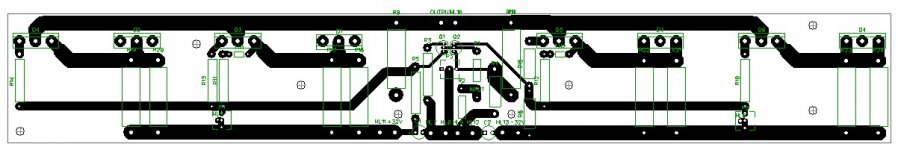
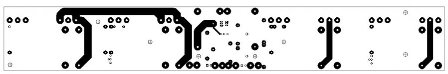
Please let me know if you see any major issue with this. I have created it based on layout image posted in this forum.
Component name are same as in F5 Turbo V2 circuit from Nelson Pass.
Thankyou
Hi,
Please let me know if you see any major issue with this. I have created it based on layout image posted in this forum.
Component name are same as in F5 Turbo V2 circuit from Nelson Pass.
Thankyou
Attachments
Protective Earth
Hi,
Regarding Protective earth, all 4 heat sinks, front , back and base plates connected to each other through screws. I have tested using continuity tester.
Do I still need to connect protective earth wire to individual plates?
what is the maximum resistance any two points on chassis should have so a human touching plates doesn't provide a low resistance path?
There is a specific test for UK for this, but I don't recall the details.
But I think it specifies a test current and the maximum voltage drop from exposed chassis back the the PE at the distribution board. It needs long test leads.
India is likely to be different.
But I think it specifies a test current and the maximum voltage drop from exposed chassis back the the PE at the distribution board. It needs long test leads.
India is likely to be different.
In reference to the kinds of pieces that people are building around here:
Last time I looked, the tests associate with HI POT looked at two things,
first the leakage to chassis/earth at 2200 VAC less than 10 mA, and
chassis to AC ground tested at high current, like at an amp or so.
Of course it's probably changed by now, but you need to assume that
chassis ground is not allowed to rise to any unsafe potential without
popping some safety device. A hard Earth chassis ground makes that
either something inside the amp like a breaker or fuse, or as a last resort,
the breaker/fuse in the electrical box.
So you test for < 10 mA at 2200 VAC, and see to it that there is very low
resistance from chassis to AC earth. Something less than an ohm.
In any case, better safe than sorry....
Hi,
Regarding Protective earth, all 4 heat sinks, front , back and base plates connected to each other through screws. I have tested using continuity tester.
Do I still need to connect protective earth wire to individual plates?
what is the maximum resistance any two points on chassis should have so a human touching plates doesn't provide a low resistance path?
If you are safety concerned, consider this one
Residual-current device - Wikipedia
On the bottom of the page is Regulation for India.
Its NOT replacement for fuse/braker, you steel need them.
Thankyou Andrew, Nelson and Radule
I'll connect each plate to Protective Earth and see that I have RCD not just MCB.
I'll connect each plate to Protective Earth and see that I have RCD not just MCB.
- Status
- Not open for further replies.
- Home
- Amplifiers
- Pass Labs
- F5 Turbo V2 Queries