Hi !
I am referring to the graph below.
http://www.analog.com/library/analogdialogue/archives/39-09/3909_01.gif
I see that the more the uF the lower the minimum impedance frequency.
Is there a way to calculate the Hz at which a capacitor gives the lowest impedance ?
Thanks a lot.
Regards, gino
I am referring to the graph below.
http://www.analog.com/library/analogdialogue/archives/39-09/3909_01.gif
An externally hosted image should be here but it was not working when we last tested it.
I see that the more the uF the lower the minimum impedance frequency.
Is there a way to calculate the Hz at which a capacitor gives the lowest impedance ?
Thanks a lot.
Regards, gino
You calculate anything if you have the proper parameters, here parasitic inductance is clearly resonationg with capacitance , both providing a dip at resonant frequency and then rising impedance once inductance takes over.
I guess in a home situation just sweeping and noticing impedances will be faster/better than guessing parameters not often shown in datasheets.
I guess in a home situation just sweeping and noticing impedances will be faster/better than guessing parameters not often shown in datasheets.
You calculate anything if you have the proper parameters, here parasitic inductance is clearly resonationg with capacitance , both providing a dip at resonant frequency and then rising impedance once inductance takes over.
Hi and thanks a lot for the very kind and helpful reply.
I am clearly lacking in theory. It is difficult theory. A lot of math involved 😱
I can only read some datasheets or graph.
I guess in a home situation just sweeping and noticing impedances will be faster/better than guessing parameters not often shown in datasheets.
Thanks again for the valuable advice.
In the meantime I have found figures in a datasheet here (page 8)
http://en.tdk.eu/inf/20/30/db/aec_2013/B41692_B41792.pdf
I have to explain my problem a little more.
I have issue with ripple from a psu in the range from 10 kHz to 100 kHz.
So I was wondering if some bypassing with caps could help.
But I see that I should use big uF and this could create problem to the psu.
I guess the right solution could be a LC filter but I cannot allow the consequent voltage drop.
I think I will replace the smps with another possibly less rippling.
This psu ripple is my present nightmare.
Thanks a lot again.
Kind regards, gino
The frequency of the dip depends on the inductance which depends on the lead length, so the best a datasheet can do is show what happens for a particular lead length. For all other lead lengths you have to calculate or measure.
'Bypassing' does not reduce ripple. Adding extra smoothing may help, but that requires extra R or L in series with the supply. Maybe find a better PSU?
'Bypassing' does not reduce ripple. Adding extra smoothing may help, but that requires extra R or L in series with the supply. Maybe find a better PSU?
The frequency of the dip depends on the inductance which depends on the lead length, so the best a datasheet can do is show what happens for a particular lead length. For all other lead lengths you have to calculate or measure. 'Bypassing' does not reduce ripple.
Adding extra smoothing may help, but that requires extra R or L in series with the supply. Maybe find a better PSU?
Hi and thanks a lot sincerely for the very complete and helpful explanations.
I understand that troubleshooting is a serious task for expert people.
I was thinking about a LC filter but I am worried by the voltage drop on the filter.
Current is about 1.5A and Vin 11.5VDC. I guess the voltage drop would be significant ?
I will look for a replacement.
Thanks a lot again.
Kind regards, gino
Last edited:
And Vout?Hi and thanks a lot sincerely for the very complete and helpful explanations.
I understand that troubleshooting is a serious task for expert people.
I was thinking about a LC filter but I am worried by the voltage drop on the filter.
Current is about 1.5A and Vin 11.5VDC. I guess the voltage drop would be significant ?
I will look for a replacement.
Thanks a lot again.
Kind regards, gino
Even a R-C filter can help a lot, in your case R of about 1 Ohm would drop 1.5V, add around 1000uF of C and you have a good filter above 200 Hz
Normally solid state regulators have excellent input rejection at lower frequencies. Poor rejection points at a layout problem
And Vout?
Hi !
thanks a lot for the helpful reply.
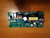
it is a hifi piece. There is a psu with output 11.5VDC/1.5A (i cannot measure the current but from the specs they say power consumption 15W) powering the circuits board.
I have used another external 12VDC psu and there is no noise issue.
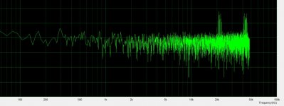
The noise start from about 20Khz up at multiple Hz (harmonics ?). Not much but it is there very clearly.
From this the idea to filter a little the original psu to keep using it and not having to rely on an external and not very handy psu.
Before replacing the internal psu of course.
Even a R-C filter can help a lot, in your case R of about 1 Ohm would drop 1.5V, add around 1000uF of C and you have a good filter above 200 Hz. Normally solid state regulators have excellent input rejection at lower frequencies. Poor rejection points at a layout problem
I think 1.5V drop is too much and unfortunately i do not see any trimmer to increase the Vout (picture attached). What leaves me surprised is that even with cheap power bricks the unit does not exhibit this kind of noise.
And for sure these psu are not high end at all.
I read that 100mV pk2pk is the norm.
It is not radiated noise from the psu because i have disconnected all the signal cables on the circuit board and the noise is still there.
It is coming out from the psu. How sad.
I am thinking to buy an encapsulated new one psu and then place it inside replacing the stock one after checking for any noise of course.
I guess that an encapsulated one should be also completely shielded while the stock one is completely open frame.
Thanks a lot again, gino
Attachments
Last edited:
Switched mode power supply common mode noise! By the look of the transformer, the switching frequency is failrly low
Switched mode power supply common mode noise!
By the look of the transformer, the switching frequency is failrly low
Hi ! thank you very much indeed for your very valuable advice.
This is very important for me because I understand now there is a design issue I have no hope to solve.
I was almost resigned to live with it thinking that the issue were instead in the circuit board and so impossible to eliminate.
Then after some searching in the web I tried another 12VDC smps by Dell, a refurbished one looking like it was coming from a garbage bin 😱. I think I paid it 10USD maybe ?
And bam ... no peaks to speak of. A noise floor nicely low and flat.
And after that others with the same result.
All very very cheap Chinese things.
This unit is intended for the pro market.
I really do not understand why they have slipped on a very trivial aspect.
From what I understand the other parts are very good.
I am thinking to put a power brick inside (they are also completely shielded and encapsulated.
I have only one issue.
If the power brick comes with a 3 wires mains in I guess I have to connect the earth to the chassis of the unit ? or leave it floating ?
Thanks a lot again.
Kind regards, gino
P.S. on a different case I have another cheaper interface also showing some noise peaks noise floor.
In that case even changing the external ps has no effect on the peaks.
I understand this kind of interfaces take the 12VDC supply and generate the needed voltages with internal DC-DC converters.
In this second case the issue is clearly on the board, so I have to live with that.
But this is not a pro unit of course and as I said much cheaper.
Last edited:
- Status
- Not open for further replies.
- Home
- Design & Build
- Parts
- Capacitors _ Impedance versus Hz