Can you post pictures and voltage measurements?
Here you go.
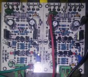
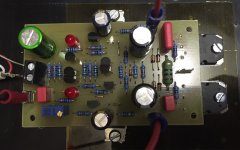
As you can see, I didn't populate the zeners, undesignated rail caps or 10R rail resistors. I used a 10uF BP cap at the input.
All voltage are measured across the componant. Rails are +-38V.
Small transistors are KSC1845/KSA992
Attachments
I am in the process of building up FX8 bimo-mod boards the my friend XRK sent me. I just received my 2sc1845 from aliexpress.com, but it turned out to be P grade and they all measure up around 225 Hfe. What Hfe did bimo design for in his FX8-mod?
If these are out of spec, I will just order some KSC1845 from digikey.
If these are out of spec, I will just order some KSC1845 from digikey.
The schematic shows BC5xx devices, but you are using KSA/KSC which have a different pinout. Is the PCB layout for the devices in the schematic or the KSA/KSC?
Here you go.
As you can see, I didn't populate the zeners, undesignated rail caps or 10R rail resistors. I used a 10uF BP cap at the input.
All voltage are measured across the componant. Rails are +-38V.
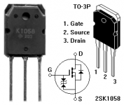
Small transistors are KSC1845/KSA992
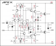
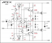
You must have Vbe on all BJT transistors about 0,6V and about 1,8V on red leds... 0,72V across 1k8 and 1,72V across 470R must be wrong...
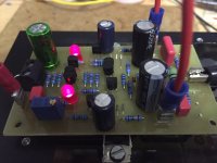
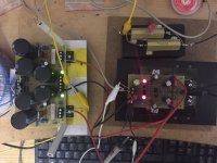
Hi Terry, I measured at my FX12. Here are the values. Maybe it helps.
Supply voltage is 38,6V. Instead the 2SA1837 / 2SC4793 I used 2SA968 I / 2SC2238. And a few more pictures.
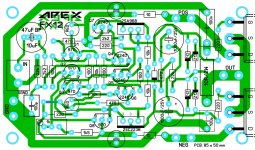
I apologize for the error in the layout. Perhaps we should publish only really tested layouts.
The layout is really not perfect. I think if I have time, I'll develop a new layout with BCxxx and Latfets on the sides, so that maybe one other pair has space.
The really good sound deserves a better layout 🙂 an I hope you can find quickly the error.
regards Olaf
Supply voltage is 38,6V. Instead the 2SA1837 / 2SC4793 I used 2SA968 I / 2SC2238. And a few more pictures.
I apologize for the error in the layout. Perhaps we should publish only really tested layouts.
The layout is really not perfect. I think if I have time, I'll develop a new layout with BCxxx and Latfets on the sides, so that maybe one other pair has space.
The really good sound deserves a better layout 🙂 an I hope you can find quickly the error.
regards Olaf
Attachments
Hi Terry, I measured at my FX12. Here are the values. Maybe it helps.
Supply voltage is 38,6V. Instead the 2SA1837 / 2SC4793 I used 2SA968 I / 2SC2238. And a few more pictures.
I apologize for the error in the layout. Perhaps we should publish only really tested layouts.
The layout is really not perfect. I think if I have time, I'll develop a new layout with BCxxx and Latfets on the sides, so that maybe one other pair has space.
The really good sound deserves a better layout 🙂 an I hope you can find quickly the error.
regards Olaf
Nice work and yes this VAS can drive 2 or 3 ouput pairs.
Regards
I am in the process of building up FX8 bimo-mod boards the my friend XRK sent me. I just received my 2sc1845 from aliexpress.com, but it turned out to be P grade and they all measure up around 225 Hfe. What Hfe did bimo design for in his FX8-mod?
If these are out of spec, I will just order some KSC1845 from digikey.
The THD will reduce slightly, but it is OK.
As you can see, I didn't populate the zeners,
Without the protection zeners you may get higher than (around) 20V across Gate-Source (is that 38V??) and burn the LATFET.
Without the protection zeners you may get higher than (around) 20V across Gate-Source (is that 38V??) and burn the LATFET.
Those zeners are built into the LatFets.
Attachments
Those zeners are built into the LatFets.
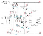
Yes, but in unknown environment there could be a situation where the internal zener failed. But my main point was: you could measure the Vgs (that 38V label you put on the gate was an error?).
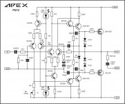
That 38V does not belong there. It is misplaced. I understand the confusion now. Here is a corrected version
Attachments

Last edited:
The THD will reduce slightly, but it is OK.
Sorry, I mean THD will slightly increase with lower hFE.
Those zeners are built into the LatFets.
While lateral MOSFETS that you are using may have internal protection diodes, all lateral MOSFETS don't come with them by default. Current Semelab lateral MOSFET devices don't have internal protection diodes. Old Exicon double die lateral MOSFETS also don't have internal protection diodes.
That 38V does not belong there. It is misplaced. I understand the confusion now. Here is a corrected version
Is that 0.75V on the input LTP tail also a mistake? Because it is inconsistent with the 3V across (1k8+1kpot)... With V=3, the minimum current is at the maximum resistance, so I=3/(2k8)= slightly above 1mA. But 0.75v/1k8 is much below 1mA (even if it is a typo, 1.75v/1k8 is still below 1mA, which is not possible or inconsistent).
Is that 0.75V on the input LTP tail also a mistake? Because it is inconsistent with the 3V across (1k8+1kpot)... With V=3, the minimum current is at the maximum resistance, so I=3/(2k8)= slightly above 1mA. But 0.75v/1k8 is much below 1mA (even if it is a typo, 1.75v/1k8 is still below 1mA, which is not possible or inconsistent).
I misread my own writing. The 1k8 measures 2.5V
Here is the schematic with VBE measurements in blue. 1.7V across 470R is correct.
Still have oscillation. Maybe the outputs need more compensation. I will try that and get back.
Add 10pF and 33pF for more compensations.
Attachments
In FX12 is there an advantage to use BC546/556 over KSC1845/KAS992 i have both brand....
Marc
Marc
- Home
- Amplifiers
- Solid State
- 100W Ultimate Fidelity Amplifier