just an idea...
any guess???
It wouldn't be AX11 anymore... May be AXP3A? 😛

It wouldn't be AX11 anymore... May be AXP3A? 😛
May be AX11S
Attachments

Nice work Olafk!
That was fast. What is the problem with the offset? It's not stable? Did you match the input transistors? With matched inputs - the pot can probably bypassed.
That was fast. What is the problem with the offset? It's not stable? Did you match the input transistors? With matched inputs - the pot can probably bypassed.
Last edited:
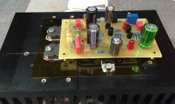
I get started with the FX12. The amplifier operates. The sine looks good. Problem is an offset independently of the position of the pot of 150mV.
I will see what I can do the next few days that way.
regards Olaf
Nice work... can you post voltage measurements on 2k2 and 220R resistors in LTP colectors?
Regards
measurements
Hi, here are some measurements. I've corrected the offset by changing the 470R resistors. But I think now the amplifier is underbiased.
Advice are welcome 🙂
But the sound is very, very good. Deep, powerful bass, well balanced mids and transparent beautiful highs.
Regards Olaf
Hi, here are some measurements. I've corrected the offset by changing the 470R resistors. But I think now the amplifier is underbiased.
Advice are welcome 🙂
But the sound is very, very good. Deep, powerful bass, well balanced mids and transparent beautiful highs.
Regards Olaf
Attachments
Hi, here are some measurements. I've corrected the offset by changing the 470R resistors. But I think now the amplifier is underbiased.
Advice are welcome 🙂
But the sound is very, very good. Deep, powerful bass, well balanced mids and transparent beautiful highs.
Regards Olaf
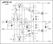
Bias is set by voltage on 1N4148 diode and it is fixed, VAS current can not change bias.
Regards
Hi Mile,
ok, trouble misunderstood 🙂.
I could not match the transistors. I bought some time ago both types and got per type transistors with equal gain but very different between the types.
Are for now still improvements possible?
regards Olaf
ok, trouble misunderstood 🙂.
I could not match the transistors. I bought some time ago both types and got per type transistors with equal gain but very different between the types.
Are for now still improvements possible?
regards Olaf
Hi Olaf,
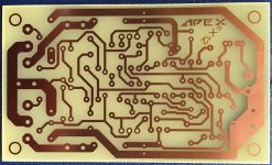
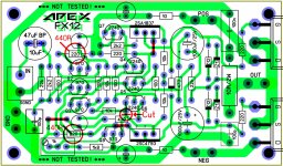
There is an error in the layout. You have the base of the 2SC4793 connected to the base of the 2240 and the emitter of the 970. It should only connect to the 970.
There is an error in the layout. You have the base of the 2SC4793 connected to the base of the 2240 and the emitter of the 970. It should only connect to the 970.
Attachments
Last edited:
Hi Still,Hi Olaf,
There is an error in the layout. You have the base of the 2SC4793 connected to the base of the 2240 and the emitter of the 970. It should only connect to the 970.
Thanks alot. And I have repeatedly tested it ... 🙄
You've completely right. But how can the amplifier then sound so good???
I will test it as soon as possible.
regards Olaf
I was wondering the same thing. I didn't come by the error by chance. I have the amp built and struggled for over a day trying to find what I did wrong until I sat down with the schematic and the layout and went over both of them with a highlighter. That is when I found it. I have only tested it without the outputs so far. If I have time I will solder in the outputs and mount it to a heatsink and do some official testing.
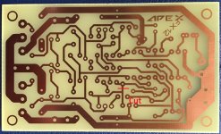
This layout was a little but of a struggle because the traces are very close together in places and I heated them a little too long so I had to do a bit of grinding to eliminate solder bridges. It looks like you have a newer layout that seems to have addressed some of these issues.
Blessings, Terry
This layout was a little but of a struggle because the traces are very close together in places and I heated them a little too long so I had to do a bit of grinding to eliminate solder bridges. It looks like you have a newer layout that seems to have addressed some of these issues.
Blessings, Terry
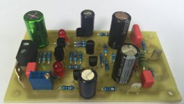
Hi, I have just tried it. The amplifier now works great. The changed resistors are reset to 470R. The circuit so is back to the original.
The 220R resistor in the bottom left of your picture must be on 220R.
regards Olaf
The 220R resistor in the bottom left of your picture must be on 220R.
regards Olaf
Not to forget: Offset is now 7mV.
You're right, the layout is a bit changed. I measure a few things tomorrow and then post layout with the correct values.
You're right, the layout is a bit changed. I measure a few things tomorrow and then post layout with the correct values.
Last edited:
Hi, I have just tried it. The amplifier now works great. The changed resistors are reset to 470R. The circuit so is back to the original.
The 220R resistor in the bottom left of your picture must be on 220R.
regards Olaf
Yes you are correct.
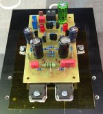
I have mine playing. Sound is distorted. Looks like oscillation on the scope. Also Both channel are drawing 40mA per rail. Just the front end and VAS draw 20mA so the outputs are biases very low. I don't have the zeners installed but I believe those are just for protection. Both channels sound the same so if I have an error it is on both channels but I have triple checked all the values due to the layout error.
I have mine playing. Sound is distorted. Looks like oscillation on the scope. Also Both channel are drawing 40mA per rail. Just the front end and VAS draw 20mA so the outputs are biases very low. I don't have the zeners installed but I believe those are just for protection. Both channels sound the same so if I have an error it is on both channels but I have triple checked all the values due to the layout error.
Can you post pictures and voltage measurements?
- Home
- Amplifiers
- Solid State
- 100W Ultimate Fidelity Amplifier