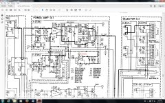
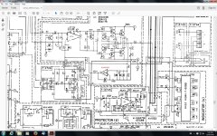
I noticed the Sansui A-909 go in and out of protection so I measured the DC offset at the speaker posts. I got 25mv on right channel and 230mv on left channel. Where do I look to fix it? I know opamp NJM4558D has something to do with it, could the opamp be out of spec? The voltage amplifier is not the original STK3082 II going by the schematic.The one in it now is STK3102 II.
Attachments
Last edited:
Large manufacturers often did without offset pots by carefully sellecting & matching their parts. 230 mv is outside normal range.
4558 are no more likely to fail than any of these other parts. Usually if an op amp fails the output whangs to the rail voltage.
I don't see any heat sense parts unless vr1 the 1 k with a slash through it, is located on the heat sink with the output transistors. If it was remote, oxidized connections to it could be the problem. If the op amp is in a socket, oxidation on the pins might be causing the problem. Reseat all connectors. If that doesn't work you have to slog through the circuit with a DVM tracing the offset voltage to the source. Op amps used in linear, the inputs and outputs should all be at the same voltage with the amp input shorted.
Last edited:
Large manufacturers often did without offset pots by carefully sellecting & matching their parts. 230 mv is outside normal range.
4558 are no more likely to fail than any of these other parts. Usually if an op amp fails the output whangs to the rail voltage.
I don't see any heat sense parts unless vr1 the 1 k with a slash through it, is located on the heat sink with the output transistors. If it was remote, oxidized connections to it could be the problem. If the op amp is in a socket, oxidation on the pins might be causing the problem. Reseat all connectors. If that doesn't work you have to slog through the circuit with a DVM tracing the offset voltage to the source. Op amps used in linear, the inputs and outputs should all be at the same voltage with the amp input shorted.
The 1k VR is for bias adjustment. I have some 1k ohm 25 turn sealed VRs to install maybe they will be more precise?
The 4558 is being used as a servo and so should hold the output to within a few mv of zero. For no good reason (other than they have a reputation) I would perhaps be looking at that STK. It might also be worth sticking a scope on the output and checking there is no oscillation going on.
If the 1k is a pot instead of a ntc resistor, then oxide on the pot wiper could be the problem. I clamp idle curent pots with a diode to prohibit idle current runaway if the wiper oxidizes. In some cases, a schottky diode.
Of course, I am not in business. That extra $.05 diode x2 might cause a manufacturer to lose a sale. They wouldn't want that. And many manufacturers would want their gear to blow up in 4-5 years anyway. Commercial repairmen the same way - 5 years and a blown output transistor stack makes a repeat customer. That is why IMHO 500 hour e-caps outsell 10000 hour service life caps . Farnell has even dropped the service life rating from the selector table; you have to ask for it now. Mouser you always had to download the datasheet to separate out the trash from the long life parts.
Of course, I am not in business. That extra $.05 diode x2 might cause a manufacturer to lose a sale. They wouldn't want that. And many manufacturers would want their gear to blow up in 4-5 years anyway. Commercial repairmen the same way - 5 years and a blown output transistor stack makes a repeat customer. That is why IMHO 500 hour e-caps outsell 10000 hour service life caps . Farnell has even dropped the service life rating from the selector table; you have to ask for it now. Mouser you always had to download the datasheet to separate out the trash from the long life parts.
Last edited:
The 4558 is being used as a servo and so should hold the output to within a few mv of zero. For no good reason (other than they have a reputation) I would perhaps be looking at that STK. It might also be worth sticking a scope on the output and checking there is no oscillation going on.
I found a broken solder joint on C15 electro 47uf 63v that fixed that side,it now reads under 1mv. I still have 12mv on the other side,Ill recheck the bias settings and see if its out a bit just in case that affects it as well? Ive gone over most of the main board and reflowed the joints.This amp has about the worst wave soldering Ive ever seen,just about every third solder joint has a ring around it! My oscilloscope is busted and has been for years,it has an arc in the high voltage power supply that Ive never been able to figure out,I think its probably the flyback transformer has had it? Its a never ending story! lol
Attachments

You would think that in the year 2016 society would be so far advanced by now but corporate greed and right wing ideoligy is still here whittling away at reason.If the 1k is a pot instead of a ntc resistor, then oxide on the pot wiper could be the problem. I clamp idle curent pots with a diode to prohibit idle current runaway if the wiper oxidizes. In some cases, a schottky diode.
Of course, I am not in business. That extra $.05 diode x2 might cause a manufacturer to lose a sale. They wouldn't want that. And many manufacturers would want their gear to blow up in 4-5 years anyway. Commercial repairmen the same way - 5 years and a blown output transistor stack makes a repeat customer. That is why IMHO 500 hour e-caps outsell 10000 hour service life caps . Farnell has even dropped the service life rating from the selector table; you have to ask for it now. Mouser you always had to download the datasheet to separate out the trash from the long life parts.

With the bias trimmer in the B-E side of the circuit it is fail-safe. If the wiper goes open the bias goes full cold.
Craig
Craig
I found a broken solder joint on C15 electro 47uf 63v that fixed that side,it now reads under 1mv. I still have 12mv on the other side,Ill recheck the bias settings and see if its out a bit just in case that affects it as well? Ive gone over most of the main board and reflowed the joints.This amp has about the worst wave soldering Ive ever seen,just about every third solder joint has a ring around it! My oscilloscope is busted and has been for years,it has an arc in the high voltage power supply that Ive never been able to figure out,I think its probably the flyback transformer has had it? Its a never ending story! lol
Good stuff. Any rail decoupler that's open circuit around one of those STK's could cause it to do all kinds of things.
12mv offset is absolutely fine as long as its stable. The 4558 is an odd choice to use for a servo... maybe we've got more picky over the years but nowadays nothing other than a FET or CMOS device would qualify. The TL072 is a favourite.
And yes, I remember your scope saga.
I check for oscillations with a VOM on the 20 vac then the 2 vac scale. A DC blocking cap is used in series with the ground probe. If AC is present, changing from a .047 uf cap for normal checks to a 390 pf cap, will show ultrasonic oscillations. Music won't go through a 390 pf cap.
I can't keep used scopes working either. The boards are glued in my BK 2120, which is chock-full-a expired e-caps.
I can't keep used scopes working either. The boards are glued in my BK 2120, which is chock-full-a expired e-caps.
Good stuff. Any rail decoupler that's open circuit around one of those STK's could cause it to do all kinds of things.
12mv offset is absolutely fine as long as its stable. The 4558 is an odd choice to use for a servo... maybe we've got more picky over the years but nowadays nothing other than a FET or CMOS device would qualify. The TL072 is a favourite.
And yes, I remember your scope saga.
I reflowed every solder joint I came across. Now its rock steady 1.6 ohms on the right channel and 1.9 ohms on the left. I cant imagine how dodgy solder joints or oxidized VR pots etc,can add DC to the circuit though,how would that work or is it some quantum tunnelling field effect? Ive got some TL072s but theres no point in using one of those now that its working OK, is there ?
Last edited:
With the bias trimmer in the B-E side of the circuit it is fail-safe. If the wiper goes open the bias goes full cold.
Craig
Thats good to know? Thanks for that mate.
Ive got some TL072s but theres no point in using one of those now that its working OK, is there ?
Its obviously working OK so keep it original.
I looked again at the circuit, and I think the reason they can get away with using a 4558 is because the impedances around it are so low (and so no opamp offset errors due to bias currents creep in). Today and we would be using 1meg resistors and much smaller film caps in the servo.
You certainly know your stuff Mooly! I downloaded: (Op amps Handbook) from freeinfosociety.com to try and understand the finer details of these things? Its a real eye opener and really interesting to see what you can do with them? If the local shop has the 4558 or 4516 when it opens tomorrow, Ill install it and let you know how it went.Im pretty confident thats where the noise is coming from because I reinstalled the links and the noise was back!
Last edited:
Thanks 🙂 Yes, opamps are very useful devices.
One rule will help you understand them:
'the output of an opamp with feedback will do whatever it takes to keep the difference in voltage as seen between the inputs at zero'. Notice the word difference.
The 'with feedback' bit covers all audio applications (but not things like comparators)
One rule will help you understand them:
'the output of an opamp with feedback will do whatever it takes to keep the difference in voltage as seen between the inputs at zero'. Notice the word difference.
The 'with feedback' bit covers all audio applications (but not things like comparators)
Thanks 🙂 Yes, opamps are very useful devices.
One rule will help you understand them:
'the output of an opamp with feedback will do whatever it takes to keep the difference in voltage as seen between the inputs at zero'. Notice the word difference.
The 'with feedback' bit covers all audio applications (but not things like comparators)
Inputs at zero? What does that mean?
It means if you put your meter across the two inputs, you will always see 0.00 volts, even though both inputs may themselves be at some voltage above or below ground.
It means if you put your meter across the two inputs, you will always see 0.00 volts, even though both inputs may themselves be at some voltage above or below ground.
Oh! OK thanks Mooly.🙂
OK 🙂
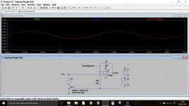
Just try working the voltages out for a simple opamp gain stage and it will all make sense.
This shows the red and green traces corresponding to the two inputs as being overlaid (so the difference is zero). The output has done what is needed to bring the inverting input up to the same voltage as the non inverting.
Attachments
- Home
- Amplifiers
- Solid State
- No DC Offset Adjustment Pots.