High-gain global NFB loop is not the only way of achieving high linearity. And not the best one. A good point for discussion.
In the same PowerAmp the introduction of the second and subsequent feedback loops leads to loss of linearity. Other ways of search of linearity is very interesting. If you consider that the cascade of common-emitter contributes to 15% distortion at small depths NFB. At the same time the cascades of the discussing amplifier from the output OpAnp contribute 0.25% of distortion when NFB coverage to the depth of about 60 dB (gain OpAmp).
Last edited:
Sorry, can't bring myself to believe in so much high indicators in this schematic audio | Project VERTICAL audio | Project NS-OPS. Yesterday I tried to squeeze something from a much more sophisticated CFA circuit, but attempts to squeeze at least 0,000.4% failed. A real amplifier will make more of a distortion than an idealized model.
See it here:
VERTICAL CFA + NS-OPS
Since that time it's re-built and re-measured many times. Also tested with high capacitive loads.
If you look at the schematic carefully, you will see some cool circuit arrangements, ensuring very high linearity in both voltage amplifier and OPS.
Now I'm planning to test a balanced configuration with the tube Wilson phase splitter at the input (inspired by John Broskie). I like tubes at the input 😉
And then we test the same balanced configuration, but with VFA modules and lower gain multi-loop feedback - definitely higher distortion, but very tube-like sound is expected 😎
http://www.diyaudio.com/forums/atta...ng-some-old-ideas-1970s-ips-ops-01-sch-02.jpgSee it here:
VERTICAL CFA + NS-OPS
Since that time it's re-built and re-measured many times. Also tested with high capacitive loads.
If you look at the schematic carefully, you will see some cool circuit arrangements, ensuring very high linearity in both voltage amplifier and OPS.
Now I'm planning to test a balanced configuration with the tube Wilson phase splitter at the input (inspired by John Broskie). I like tubes at the input 😉
And then we test the same balanced configuration, but with VFA modules and lower gain multi-loop feedback - definitely higher distortion, but very tube-like sound is expected 😎
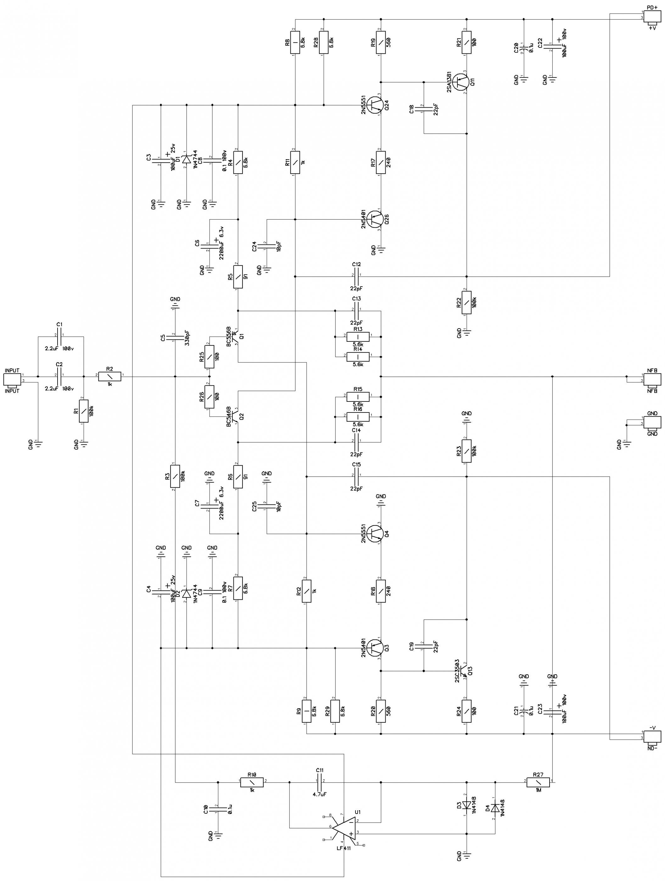
Here with simulator measure the distortion at the bases of Q11 and Q13. They are there to 10%. What's the reason? Because it cascades with common emitter, they strongly distort the signal and shift its phase. Need a very, very deep feedback to reduce these distortions at least to a little bit tolerable level of 0.001% - 80 dB amplification of the first cascade. This increase is not there - hence the large distortion.
To obtain a nice ear distortions in the signal are not provided for the forgetful a sound engineer, there are lots of cheaper ways. Unfortunately I do not think the right to make the signal distortion that are not provided by singers, musicians and sound engineers.
At the output of the voltage amplifier needs to be installed cascades with common base with high linearity and less phase shift.
See here the work of Sergey Ageyev and Leonid Zuev.
Electrolytic capacitors C6, C7 are very noisy at low frequencies. Shouldn't have to give the more stable differential circuitry.
http://www.diyaudio.com/forums/atta...ting-some-old-ideas-1970s-ips-ops-101-sch.jpg
Using C9, C10 in the signal to get distortion from the power rails.
Last edited:
http://www.diyaudio.com/forums/atta...ng-some-old-ideas-1970s-ips-ops-01-sch-02.jpg
Here with simulator measure the distortion at the bases of Q11 and Q13. They are there to 10%. What's the reason? Because it cascades with common emitter, they strongly distort the signal and shift its phase. Need a very, very deep feedback to reduce these distortions at least to a little bit tolerable level of 0.001% - 80 dB amplification of the first cascade. This increase is not there - hence the large distortion.
To obtain a nice ear distortions in the signal are not provided for the forgetful a sound engineer, there are lots of cheaper ways. Unfortunately I do not think the right to make the signal distortion that are not provided by singers, musicians and sound engineers.
At the output of the voltage amplifier needs to be installed cascades with common base with high linearity and less phase shift.
See here the work of Sergey Ageyev and Leonid Zuev.
Electrolytic capacitors C6, C7 are very noisy at low frequencies. Shouldn't have to give the more stable differential circuitry.
http://www.diyaudio.com/forums/atta...ting-some-old-ideas-1970s-ips-ops-101-sch.jpg
Using C9, C10 in the signal to get distortion from the power rails.
I would like to hear your opinion of this amp. What you said about audio amps it's very similar to mine thinking.
Attachments
I would like to hear your opinion of this amp. What you said about audio amps it's very similar to mine thinking.
I simulated Your circuit design. The first: is a resistive load input cascade R5, R6. As can be seen from 120W-TT-CFA-triple-TPOIC-efVAS-currmirror.asc, you realized it too. Second - distortion input stage is too high. They are not eliminated feedback. Perhaps this type of input stage will have to be replaced.
High voltage transistors like 3502/1380 lose the gain current and the frequency characteristics when the voltages at the collector below 7...8 volts, which leads to distortion at the maximum output power, when they are forced to work at low voltages at the collector. Therefore, the voltage of the voltage amplifier should be separate and at 15 V above the supply voltage of the corresponding shoulder of the output stage.
Imperfect and incomplete, after my research, the circuit design is loaded.
Distortion is below 0,000.4% 20 kHz 40 V / 8 Ohms failed to achieve.
Attachments
Last edited:
Distortion is below 0,000.4% 20 kHz 40 V / 8 Ohms failed to achieve.
Failed to get level Distortion is below 0,000.4% 20 kHz 40 V / 8 Ohms.
Maybe that makes it clearer:I'll try again:
what does this mean?:
Failed to get level Distortion is below 0,000.4% 20 kHz 40 V / 8 Ohms.
I simulated Your circuit design. The first: is a resistive load input cascade R5, R6. As can be seen from 120W-TT-CFA-triple-TPOIC-efVAS-currmirror.asc, you realized it too. Second - distortion input stage is too high. They are not eliminated feedback. Perhaps this type of input stage will have to be replaced.
High voltage transistors like 3502/1380 lose the gain current and the frequency characteristics when the voltages at the collector below 7...8 volts, which leads to distortion at the maximum output power, when they are forced to work at low voltages at the collector. Therefore, the voltage of the voltage amplifier should be separate and at 15 V above the supply voltage of the corresponding shoulder of the output stage.
Imperfect and incomplete, after my research, the circuit design is loaded.
Distortion is below 0,000.4% 20 kHz 40 V / 8 Ohms failed to achieve.
I see here problem in communication (language).
My simulation shows THD at 20 kHz and 40 Vp/8 ohm (100W) 0.000094%, and this is lower then 0,000.4% if I understand it correctly.
Harmonic Frequency Fourier Normalized Phase Normalized
Number [Hz] Component Component [degree] Phase [deg]
1 2.000e+04 3.952e+01 1.000e+00 -1.53° 0.00°
2 4.000e+04 2.868e-05 7.257e-07 72.64° 74.17°
3 6.000e+04 1.790e-05 4.531e-07 104.00° 105.53°
4 8.000e+04 3.958e-06 1.001e-07 119.37° 120.90°
5 1.000e+05 5.785e-06 1.464e-07 -81.81° -80.28°
6 1.200e+05 2.795e-06 7.073e-08 128.37° 129.90°
7 1.400e+05 7.023e-06 1.777e-07 178.55° 180.08°
8 1.600e+05 2.836e-06 7.176e-08 143.69° 145.22°
9 1.800e+05 1.069e-05 2.706e-07 -159.23° -157.70°
Total Harmonic Distortion: 0.000094%(0.000000%)
http://www.diyaudio.com/forums/atta...ng-some-old-ideas-1970s-ips-ops-01-sch-02.jpg
Here with simulator measure the distortion at the bases of Q11 and Q13. They are there to 10%. What's the reason? Because it cascades with common emitter, they strongly distort the signal and shift its phase. Need a very, very deep feedback to reduce these distortions at least to a little bit tolerable level of 0.001% - 80 dB amplification of the first cascade. This increase is not there - hence the large distortion.
To obtain a nice ear distortions in the signal are not provided for the forgetful a sound engineer, there are lots of cheaper ways. Unfortunately I do not think the right to make the signal distortion that are not provided by singers, musicians and sound engineers.
At the output of the voltage amplifier needs to be installed cascades with common base with high linearity and less phase shift.
See here the work of Sergey Ageyev and Leonid Zuev.
Electrolytic capacitors C6, C7 are very noisy at low frequencies. Shouldn't have to give the more stable differential circuitry.
http://www.diyaudio.com/forums/atta...ting-some-old-ideas-1970s-ips-ops-101-sch.jpg
Using C9, C10 in the signal to get distortion from the power rails.
Totally wrong analysis here as well. What 10% are you talking about? 😕
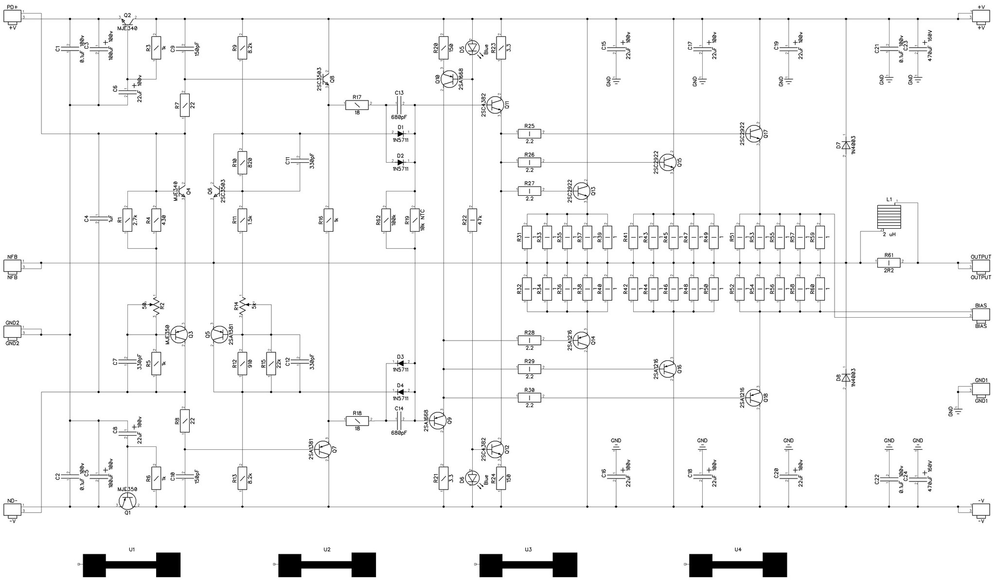
Simulated THD with open global NFB loop of the whole amplifier, including the OPS, is showing 0.022% at 20KHz (50W @ 8 ohm). There's no need to measure at Q11 and Q13 bases - you will not see anything valuable there.
Open loop gain at 20KHz is 65db. Having closed loop at 29db, we get only 36db loop gain at 20KHz. 36db = 63 times. 0.022% / 63 = 0.00035. Measured value is 0.0007%, which is ok - real life distortion is always a little bit higher than the modeled one and the output stage also adds some distortion.
I know both Sergey Ageev's and Leonid Zuev's works and I also use the common base cascades in my other designs (like here, for example - VZ-X front-end).
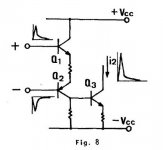
This one is inspired by "complementary differential cascade" circuit, described in detail in the copyrighted article in AES library, published in 1978 by Sansui engineers, as a good way of driving VAS - higher slew rate, lower TIM, good stability (see the picture attached). If operating points are set correctly, this kind of cascade shows an excellent combination of speed and linearity. 😎
Another success factor here is non-switching OPS, introducing much less distortion, than the normal EF2 or EF3.
"Electrolytic capacitors C6, C7 are very noisy at low frequencies." - I don't have any proof for this statement. I don't see this noise, I don't hear it, I can't measure it. No noise at low frequencies. Very low noise level in general within the whole audio bandwidth.
Cheers,
Valery
Attachments
Last edited:
No technical input here just a reality check... Are not these distortion numbers irrelevant in the face of the distortion from the speaker?
Hi Evan, on one hand - yes, speaker distortion is much higher than the one from an amplifier. On the other hand - it's different nature and different profile.
In the amplifiers, distortion profile is also very important. As we all know - even harmonics are not as bad as the odd ones in terms of subjective perception. A big number of high order harmonics is also not good. So, having some 2-nd, and a little bit of 3-rd - it's no problem. If the 2-nd one is at the level of -80-100db, the 3-rd one -100-105db and all the rest are barely visible at the noise level - it's an excellent amplifier, presuming all the other things are also good.
Some kinds of distortion, like crossover for example, are very bad. Crossover distortion with its "shelf" close to zero crossing, generates a countless number of high order components, making the output signal really harsh. So, some tube amplifier, having THD at 0.1%, with dominant 2-nd harmonic and some 3-rd one, will sound incomparably better, than a transistor one, having the same 0.1%, but caused by crossover, as a result of under-biasing, for example.
I'm trying to say, that low THD number is good, but we also need to know the profile and extremely low THD should not be the only goal for the designer. We all know, that it's possible to achieve extremely low THD number with "blameless" topology. But we may have issues with the slew rate, transients handling, etc. if we don't address them properly.
0.4% of distortion is enormous.Distortion is below 0,000.4% 20 kHz 40 V / 8 Ohms failed to achieve.
Maybe that makes it clearer:
Failed to get level Distortion is below 0,000.4% 20 kHz 40 V / 8 Ohms.
Why are you using 4 leading zeros?
I simulated Your circuit design. The first: is a resistive load input cascade R5, R6. As can be seen from 120W-TT-CFA-triple-TPOIC-efVAS-currmirror.asc, you realized it too. Second - distortion input stage is too high. They are not eliminated feedback. Perhaps this type of input stage will have to be replaced.
High voltage transistors like 3502/1380 lose the gain current and the frequency characteristics when the voltages at the collector below 7...8 volts, which leads to distortion at the maximum output power, when they are forced to work at low voltages at the collector. Therefore, the voltage of the voltage amplifier should be separate and at 15 V above the supply voltage of the corresponding shoulder of the output stage.
Imperfect and incomplete, after my research, the circuit design is loaded.
Distortion is below 0,000.4% 20 kHz 40 V / 8 Ohms failed to achieve.
I simulated your changes and distortion is much higher then my original amp.
THD at 20 kHz and 100W/8 for your changed amp is 0.001449% even with active load, and my original is 0.000094%.
You improvement is not improvement, just changes for no reason. Your compensation is overcompensated and ULGF is down from 3.6 Mhz(mine) to 737 kHz, with no better Phase Margin and Gain Margin. You did not try to understand my compensation, and use of active load did not improve distortion at 20 MHz just at frequencies below 1 kHz. In mine example with active load distortion stayed the same at 20 kHz as with resistive load, and was close to zero at low frequencies, and I decided that I don't need active load.
You can learn much hear from Valery and others.
Valery,
Thanks for the explanation. I'm working on putting together your NS-OPS. I expect the results to be excellent as usual.
Thanks for the explanation. I'm working on putting together your NS-OPS. I expect the results to be excellent as usual.
0.4% of distortion is enormous.
Why are you using 4 leading zeros?
Are you a robot? Certainly not a flexible person (intellectually).

😀 In the eastern of the Europe , the "," it is the "." and vice versa. So, we have in fact 0.0004%
Yes, I am familiar with the "continental" use of comma as a decimal point. It is usually easy to tell what is intended.😀 In the eastern of the Europe , the "," it is the "." and vice versa. So, we have in fact 0.0004%
But he wrote using both the comma separator AND the decimal place in a few posts.
So it's not a typing error. He really means to write 0,000.4%
So, which is the comma separator and which is the decimal point?
here's an extract from his post where I don't see any ambiguity
He is using the dot as the decimal place.contribute 0.25% of distortion
Last edited:
- Status
- Not open for further replies.
- Home
- Amplifiers
- Solid State
- Several schemes