I run 240VAC, 1.25A slow blow, 1xCL-60, 400VA/2x18V Toroidy Audio Grade, 2x22mF, 0.1175Ohm, 3x22mF
I use CL60 and I live in 220Vac mains, so it works.It is good for 110/120Vac
But it is too low in value for 240Vac.
When Papa put it on his schematic, better no disagreement with it 😎
Then it follows that you are a lucky Builder that is not suffering nuisance blowing of your close rated mains fuse.I use CL60 and I live in 220Vac mains, so it works.
When Papa put it on his schematic, better no disagreement with it 😎
And the same luck applies to Elfishi, although in his case the higher inductance of the "audio grade" toroid may well be helping with it's very slightly higher primary resistance also helping avoid nuisance blowing.
Last edited:
Hm. This could explain why I have a turn-on pop everytime I start my DIY F5. I used to blow the fuse a lot, but not anymore for some reason. Fuse rating is what is recommended on the F5 schematic. I use one CL-60 with 220V. What should I use then? Three CL-60 in series?
Instead try to identify a Power Thermistor that has a much higher cold resistance and also has the energy dissipation capability required.
Three CL60 would have three times the energy dissipation of a single. I doubt any domestic amplifier would need that much.
Three CL60 would have three times the energy dissipation of a single. I doubt any domestic amplifier would need that much.
Hello
the above F5 has a 500VA trafo with two CL 60 in series after a 2.5A fuse in a 230V ac mains and it runs fine.
carlos barata
the above F5 has a 500VA trafo with two CL 60 in series after a 2.5A fuse in a 230V ac mains and it runs fine.
carlos barata
And the same luck applies to Elfishi, although in his case the higher inductance of the "audio grade" toroid may well be helping with it's very slightly higher primary resistance also helping avoid nuisance blowing.
Can you expand why the audio grade toroids come with higher inductance and primary resistance?
Thx.
They have a bigger core which operates at lower flux.
That requires more ampere turns and equates to slightly longer wire which has more resistance.
That requires more ampere turns and equates to slightly longer wire which has more resistance.
Hello everybody
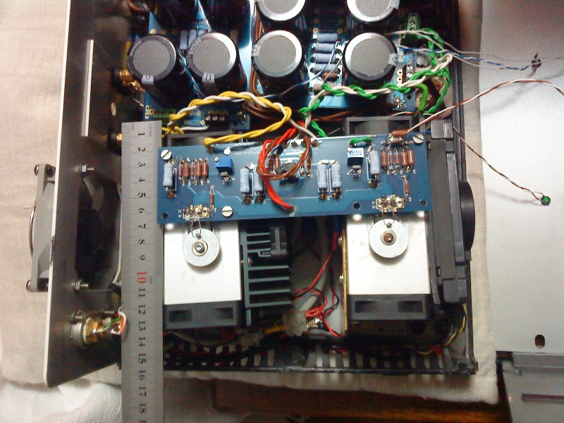
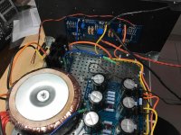
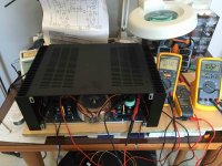
I need some help. I just finished my F5, checked the PSU (everything OK), set the bias to 90% (reading of 0,550-0,553 across R7 and R8), measured the dc offset (-3mv to 4mV fluctuating on both channels which I considered OK) and set to listen to music through two 8-ohm single drivers I connected. After a couple of notes, smoke rose up from R7 of the left channel (the one next to the 9240 mosfet) which in a couple of secs blew off followed by the R8 blown (the one next to the 240 mosfet). I use 0,47R, 1% wirewound resistors 9measured before installation to 0,7Ω??).
I'll proceed to replace the resistors with the same type (I have a bunch of them). Please any suggestions as to what could heve gone wrong and what should I check?
pictures.
what source , what interconnects , what speaker cables
when measuring under-ohm resistors , be aware of probe-to-probe resistance , in range of 0R2 to 0R5 , depending of quality of your DMM
what source , what interconnects , what speaker cables
when measuring under-ohm resistors , be aware of probe-to-probe resistance , in range of 0R2 to 0R5 , depending of quality of your DMM
I used an Auralic Vega dac connected to my Mac running Pure music (Auralic set to to digital volume control at 50 out of 100) directly connected to the F5 through XLO Signature interconnects. Speaker cable was some clip-on wires (crocodile type) connected to speakers jacks of amplifier and lugs of the drivers. The speaker cable used to connect the out of the channels to jacks was two AWG16 wound together for + and similar for -.
I hope this is helpful.
I'll try to upload two images I am not sure how this is done.
IMG_3738.jpg
IMG_3749.jpg
I hope this is helpful.
I'll try to upload two images I am not sure how this is done.
IMG_3738.jpg
IMG_3749.jpg
What happened on the right channel while the left channel went up in smoke?
Nothing happened that I could see. Unfortunately no measuring at any channel while this happened. After I switched off I measured the + and - outs of the PSU: - is 0V, + is a remaining 60mV decreasing slowly.
pictures.
what source , what interconnects , what speaker cables
when measuring under-ohm resistors , be aware of probe-to-probe resistance , in range of 0R2 to 0R5 , depending of quality of your DMM
The images I just managed to upload.
Attachments
I'll replace both resistors with same type, des older and check the mosfets. Anybody out there with suggestions?
triple check mosfet screws torque , same as isolation between mosfets and heatsink
when audio gnd is isolated from case , with ohmmeter on MOhms range , there must be infinity between mosfet mid pin (drain , metal tab on back) and case/heatsink
any residual burr on heatsink below the mosfet body could induce boom/bigbadaboom
when audio gnd is isolated from case , with ohmmeter on MOhms range , there must be infinity between mosfet mid pin (drain , metal tab on back) and case/heatsink
any residual burr on heatsink below the mosfet body could induce boom/bigbadaboom
I would disconnect everything from the power supply and check it again. Then connect the right channel and bring it up slowly with variac or use light bulb tester. Then if you have one working channel you can compare it to the left channel. I always test one channel at a time.
- Home
- Amplifiers
- Pass Labs
- An illustrated guide to building an F5