Back in December 2013, I connected an I2S-PCM board between a WaveIO and my diy tda1541a dac and also could not get it to work properly with music with a sampling rate higher than 96kHz. I puzzled over it for a while and wrote about it on this forum (post #603 to #622) but there was no resolution. Then I installed the FIFO, isolator, and clock boards and 192kHz music played successfully. I did not do anything other than install the FIFO, isolator, and clock boards.
Ian thought the problem may have been caused by a ground loop and EMC noise, and that was cut by the addition of the isolator.
I eventually upgraded the crystal oscillators to the higher frequency Crysteks and even though with the higher frequency clocks I should have been able to play 352.8kHz and 384kHz material, all I could get was music masked by a lot of noise. Since the ability to play material of these frequencies was not critical to me, I didn't pursue the matter further.
Perhaps my issues with I2S-PCM board and tda1541a dac and higher than 96kHz material may shed some light on the matter.
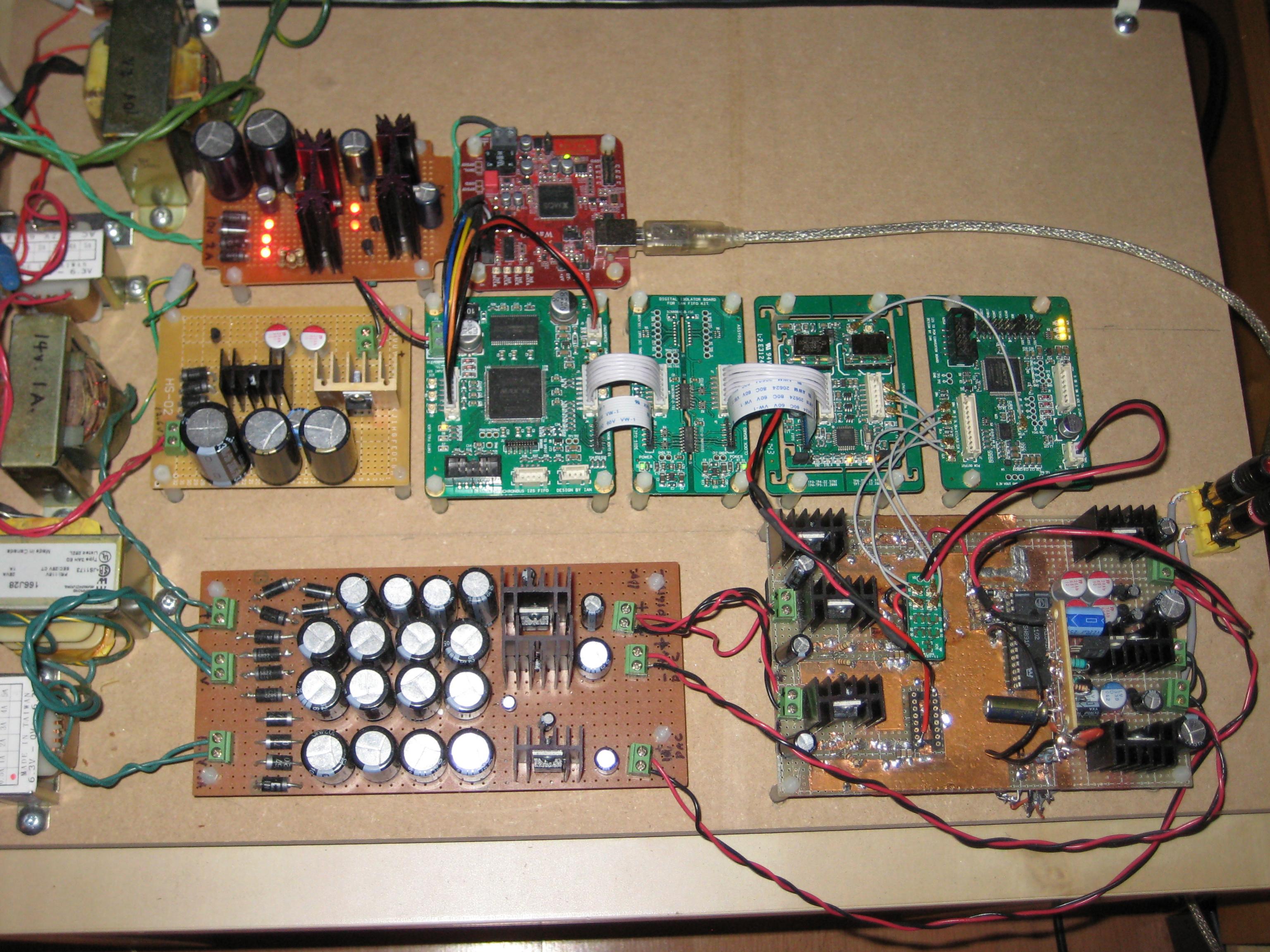
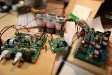
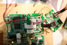
My layout and wiring:
Hi Ben,
Your set up looks very nice. Good job!
I don't have problem with 384KHz at same set up.
Yes, at 384KHz, SCK/BCK already becomes 24.576MHz. We should tread the I2S as RF signal at this frequency. Cable, returning path, grounding and PCB layout all become critical at this frequency.
Just let me re-call my old set up. I'll get back to you with what I had.
Regards,
Ian
Last edited:
TDA1541A 384KHz with PCM board and FIFO
Hi Ben,
I just re-do the 384KHz test on my TDA1541A DAC today. It was running perfect without any problem. I really love the sound of TDA1541A palying at higher Fs. Very warm and classical style.
My setup was:
Mac (384KHz upsampling) +WaveIO isolated I2S -> Ian FIFO -> Dual XO (45/49MHz) -> PCM board -> TDA1541A
The PCM board has both JOB and JHALF jumper shorted.
PCM board was designed under low jitter sync logic technology. It has bit high requirement on MCLK and I2S quality. It might be reasonable if it can not go higher Fs with XMOS. The reason I have mentioned before.
I didn't use u.fl cable in this configuration to TDA1541 (u.fl could be still better), but I paired each signal with returning path(ground wire) and grounded with careful. That's also very important for signals in RF range.
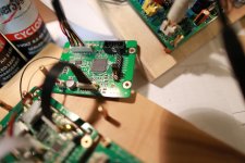
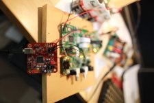
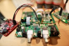
Please see pictures I took today for details.
Regards,
Ian
Hi triode_al,
I really don't know what's the physical Fs limitation of TDA1541, you can send the chip to me if you want me testing it at same cofiguration of my TDA1541A.
Regards,
Ian
Back in December 2013, I connected an I2S-PCM board between a WaveIO and my diy tda1541a dac and also could not get it to work properly with music with a sampling rate higher than 96kHz. I puzzled over it for a while and wrote about it on this forum (post #603 to #622) but there was no resolution. Then I installed the FIFO, isolator, and clock boards and 192kHz music played successfully. I did not do anything other than install the FIFO, isolator, and clock boards.
Ian thought the problem may have been caused by a ground loop and EMC noise, and that was cut by the addition of the isolator.
I eventually upgraded the crystal oscillators to the higher frequency Crysteks and even though with the higher frequency clocks I should have been able to play 352.8kHz and 384kHz material, all I could get was music masked by a lot of noise. Since the ability to play material of these frequencies was not critical to me, I didn't pursue the matter further.
Perhaps my issues with I2S-PCM board and tda1541a dac and higher than 96kHz material may shed some light on the matter.
My layout and wiring:
Hi Ben,
I just re-do the 384KHz test on my TDA1541A DAC today. It was running perfect without any problem. I really love the sound of TDA1541A palying at higher Fs. Very warm and classical style.
My setup was:
Mac (384KHz upsampling) +WaveIO isolated I2S -> Ian FIFO -> Dual XO (45/49MHz) -> PCM board -> TDA1541A
The PCM board has both JOB and JHALF jumper shorted.
PCM board was designed under low jitter sync logic technology. It has bit high requirement on MCLK and I2S quality. It might be reasonable if it can not go higher Fs with XMOS. The reason I have mentioned before.
I didn't use u.fl cable in this configuration to TDA1541 (u.fl could be still better), but I paired each signal with returning path(ground wire) and grounded with careful. That's also very important for signals in RF range.
Please see pictures I took today for details.
Regards,
Ian
I was wrong in this wild idea: the Mclock on WaveIO after isolator goes to Ians's card.
+ I now used an isolated cable for the LE.
+ I inserted inductors in all entering power lines (not just the earths).
+ and I added a parallel choke on the WaveIO power feed.
And my Macbook is always running from batteries.
Nothing helped.
Hi triode_al,
I really don't know what's the physical Fs limitation of TDA1541, you can send the chip to me if you want me testing it at same cofiguration of my TDA1541A.
Regards,
Ian
Attachments

Last edited:
Hi Ian,
I think my problem with playing 352.8kHz and 384kHz material was because of my front end and not because of any fault in the hardware after it. I was using a Pogoplug loaded with Debian and MPD, and 384kHz material played with a lot of noise and distortion.
I now have a HP Chromebox (Celeron 2955U procesor) with Debian, MPD, and Sox oversampling. I have not tried playing 384kHz material but 44.1kHz material oversampled to 352.8kHz plays clearly with only some clicks. I believe that the clicks are a computer hardware/software issue and not the fault of the WaveIO, FIFO, or I2S-PCM boards. Since I don't own any 352.8kHz or 384kHz music other than a sampler, not being able to play at those frequencies is not a problem for me.
I have very little other high resolution material but now with the Chromebox and its power to oversample 44.1kHz material to 176.4kHz, I can oversample my large library of 44.1kHz music on the fly and get rid of the tda1541a's NOS high frequency rolloff.
I agree with you - I like the sound of the tda1541a at a higher Fs and of course in simultaneous mode.
Ben
I can oversample my large library of 44.1kHz music on the fly and get rid of the tda1541a's NOS high frequency rolloff.
Ben
... and also the effect of the ultrasonic or alias image which would appear with 44.1kHz sampling rate as per (N*44.1kHz +/- 20kHz), with N = 1, 2, 3, ...
44.1 - 20 = 24.1kHz
44.1 + 20 = 64.1kHz
2*44.1 - 20 = 68.2kHz
2*44.1 + 20 = 108.2kHz
Maybe 172kHz is enough?
LH/S
I read now that the WaveIO is enabled to 192 kHz, thus I have to accept that limit.. But for now I am stuck with 88 kHz.
Condo: Thanks for remarking this. I will revisit this Kondo filter again and show my results; I have it in my DAC-player.
First prio is getting this USB stuff into 'production' (the living room).
albert
Something is not right here.. I would follow Eldams advice and look to the 1541A layout etc etc, perhaps Pedja Rogic still has some AYA PCB's for sale?.. easy to ask. They're very good, and you will have no problem with at least 192kHz.
OK, and then tell us about the Kondo filter, including where you found the info 🙂
LH/S
AYA is sold out. News feed: Pedja is designing a simultaneous mode board by the way.Something is not right here.. I would follow Eldams advice and look to the 1541A layout etc etc, perhaps Pedja Rogic still has some AYA PCB's for sale?.. easy to ask. They're very good, and you will have no problem with at least 192kHz.
OK, and then tell us about the Kondo filter, including where you found the info 🙂
LH/S
I have the Kondo design info from Jean Hiraga's book, from L'Audiophile 🙂
I have since made several filters, including notch, with the units. Even mixed P-JFet and Cmos to a good result (about 1 ohm out).
For now I will accept the 88KHz.
Have a notch filter for 176 kHz (suppress the sampling frequency: smoothes out the sine waveform, with 6 dB to suppress band noise and still flat at 20 kHz) so will have to redesign. Much harder to design at lower frequency.
But all this is OT.Did you see the passive digital filters made by Abraxalito member on his DIYAUDIO blog ? 🙂
Did you remember which l'AUDIOPHILE issue is describing the Kondo ?
Did you remember which l'AUDIOPHILE issue is describing the Kondo ?
Did you see the passive digital filters made by Abraxalito member on his DIYAUDIO blog ? 🙂
Did you remember which l'AUDIOPHILE issue is describing the Kondo ?
yes, I saw Abraxalito's smart work.
The article is: Filtre électronique trois voies, Jean Hiraga, page 201 to 218, in the book Sélection de L'Audiophile, 1985; and previously in the magazine. Surprisingly it is not in the republished and collected list of articles that appeared in l'audiophile.
I will scan it and send it; a little time; maybe start a thread.
triode_al said:"Filtre électronique trois voies, Jean Hiraga, page 201 to 218, in the book Sélection de L'Audiophile, 1985; and previously in the magazine. Surprisingly it is not in the republished and collected list of articles that appeared in l'audiophile"
What does that mean 🙂
Ian
Hi all,
I had some problems of linking and USB link non avaliable with my computer streamer !
I believed I had problems with PCM simultaneous board... then Ian gently checked and helped me : no problems here.
So I believed it was the uf-l cables, bingo some were broken because I hardly mode my DACS !
But problem was sometimes always here... Ah !
Hurra, I found the problem and hope my testimonial may help members with a bad skill as mine (if it's possible to make worst !) :
It was the tulip dip 16 sockets of the Clock pcb : I had a lot of pain to solder these tulip dip 16, mainly on the large ground vias : my soldering despite flux where fragile and putting after crystals adaptators pcb into it pushed the soldering joint at the bottom of the pcb (mainly the Gnd vias which are bigger !)!
Pain is always in the bad skill of some diyers 😱 !
Hi all,
I had some problems of linking and USB link non avaliable with my computer streamer !
I believed I had problems with PCM simultaneous board... then Ian gently checked and helped me : no problems here.
So I believed it was the uf-l cables, bingo some were broken because I hardly mode my DACS !
But problem was sometimes always here... Ah !
Hurra, I found the problem and hope my testimonial may help members with a bad skill as mine (if it's possible to make worst !) :
It was the tulip dip 16 sockets of the Clock pcb : I had a lot of pain to solder these tulip dip 16, mainly on the large ground vias : my soldering despite flux where fragile and putting after crystals adaptators pcb into it pushed the soldering joint at the bottom of the pcb (mainly the Gnd vias which are bigger !)!
Pain is always in the bad skill of some diyers 😱 !
Good to know you found the reason🙂
Clock board has a 4 layers PCB with very big ground plate. I would recommend a high power soldering station for it. It's really difficult to solder than 2 layers PCB.
Thank you for sharing.
Regards,
Ian
Last edited:
Hi all,
I had some problems of linking and USB link non avaliable with my computer streamer !
Hurra, I found the problem and hope my testimonial may help members with a bad skill as mine (if it's possible to make worst !) :
It was the tulip dip 16 sockets of the Clock pcb : I had a lot of pain to solder these tulip dip 16, mainly on the large ground vias : my soldering despite flux where fragile and putting after crystals adaptators pcb into it pushed the soldering joint at the bottom of the pcb (mainly the Gnd vias which are bigger !)!
Pain is always in the bad skill of some diyers 😱 !
Ah. We're down to real physics.
Bad joints create crystals and that can be responsible for indefinite digital behavior. [Mixing metals, solders can too. . . )
It might explain why a first XMOS implementation (and a previous board with a TDA1543) sometimes went 176 for some time & at other times only lower depending on well . . . the weather, etc etc. ?? At least surely how I routed the cables; after I upgraded the PS it never went high.
I will revisit all the connections.
And the earthing schema.
albert
I have found that poor grounding can only show up at higher speeds. I ended up spending a lot of time trying to figure this out and almost gave up if not for Eldams tips🙂 you need to look at every connection and try and understand if you have a loop, it can be difficult to see sometimes.
I have found that poor grounding can only show up at higher speeds. I ended up spending a lot of time trying to figure this out and almost gave up if not for Eldams tips🙂 you need to look at every connection and try and understand if you have a loop, it can be difficult to see sometimes.
I will rewire. I had the red baron PCB, noted it has no ground connection on the I2S, all is floating from the outside. I added a ground strip to land the isolated/shielded I2S connections but also there I got no high frequencies throughput, maybe this is the problem.
It will take time.
Maybe I will first install another DAC i have (made by marantz) that has the TDA1541 running at 382 kHz . . . so I will take some time.
Naway, I now see the TDAboard as the problem giver, not the PCMboard.
albert
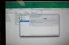
Further to my problem with oversampling to 352.8kHz with ticks and pops in the music, I have finally determined that it was a oversampling software issue. Lucien's WaveIO, Ian's FIFO and I2S-PCM boards, and my TDA1441a dac are now playing music oversampled to 352.8kHz with no issues.
The problem was with one of my SOX oversampling parameters. I use a SOX setup in MPD where I choose a bunch of parameters, and it was the bandwidth parameter that was causing the pop and click problem. I found that out by trial and error changing SOX parameters. It ended up that only with a bandwidth of 98%+/- that the music was clean with no pops. I ended up with a final bandwidth of 97.9%.
The problem was with one of my SOX oversampling parameters. I use a SOX setup in MPD where I choose a bunch of parameters, and it was the bandwidth parameter that was causing the pop and click problem. I found that out by trial and error changing SOX parameters. It ended up that only with a bandwidth of 98%+/- that the music was clean with no pops. I ended up with a final bandwidth of 97.9%.
Further to my problem with oversampling to 352.8kHz with ticks and pops in the music, I have finally determined that it was a oversampling software issue. Lucien's WaveIO, Ian's FIFO and I2S-PCM boards, and my TDA1441a dac are now playing music oversampled to 352.8kHz with no issues.
The problem was with one of my SOX oversampling parameters. I use a SOX setup in MPD where I choose a bunch of parameters, and it was the bandwidth parameter that was causing the pop and click problem. I found that out by trial and error changing SOX parameters. It ended up that only with a bandwidth of 98%+/- that the music was clean with no pops. I ended up with a final bandwidth of 97.9%.
Hi Ben Mah,
Glad to know you figure out the issue finally. Good job!
Thank you for sharing your solution with us. I just found my old TDA1541 chip (no A), I'll try the maximal Fs working with PCM board to see what's the physical limitation of 1541 once I get time.
Enjoy your music!
Ian
- Home
- Source & Line
- Digital Line Level
- Drive NOS AD1865/62,PCM1704/02/63,TDA1541 from FIFO: Universal I2S-PCM driver board