If you are looking for an external, non-ncore-specific unit, there are of course lots of designs and products out there already - no need to come up with a completely new one.
Besides, fiddling with a supposedly "finished" product is what DIY is all about... 🙂
I looked around already for some kits and/or universal versions and found only a few, mostly overprized for what they are supposed to do: 12VDC in at ~ 5mA = Power On. A 12VDC relay version usually draws to much power already for this purpose, because those 12V trigger circuits on preamps etc usually provide only about 125 - 150 mA max for that purpose, which is just about the input current of one 12VDC relay coil. Even the DIY market here doesn't offer anything, at least to my knowledge.
Lucky You 🙂
I got only three amp modules (brand new from Hypex), but they vary already quite "wildly" judging by the measurements. Might have happened at the factory or during transport (rough handling ?) though or been influenced by the PSU, who knows...
But this should not be/cause a problem for a DIY module if it has been anticipated...
Would like to see / know, what aging does to them (the adjustements/offset)...
Last edited:
No as discussed before would require a external positive voltage to hold the SMPS off in stand by. This way requires minimal components its small, reliable and is self powered.Wouldn't it make more sense to trigger the SMPS standby instead of using a triac "circuit breaker" approach?
@tier3 I'm not a liberty to discuss such matters here!
Last edited:
All I know is that the 8 units I have were well within tolerances when I got them, and still seem to have remained so.
Lucky You 🙂
I got only three amp modules (brand new from Hypex), but they vary already quite "wildly" judging by the measurements. Might have happened at the factory or during transport (rough handling ?) though or been influenced by the PSU, who knows...
But this should not be/cause a problem for a DIY module if it has been anticipated...
Would like to see / know, what aging does to them (the adjustements/offset)...
PS.: Forgot the quote... 🙄
No as discussed before would require a external positive voltage to hold the SMPS off in stand by.
Yes - so do you go for an external power supply (pretty much any wall wart lying around would do), or an external switching circuit? I prefer to use the smps standby circuitry already there in the smps, instead of brutally jerking the power 🙂
But how do golden ear audiophiles feel about a rather non-linear triac in series with their special, expensive power cord? (hint: don't tell them 🙂 ).This way requires minimal components its small, reliable and is self powered!
I looked around already for some kits and/or universal versions and found only a few, mostly overprized for what they are supposed to do: 12VDC in at ~ 5mA = Power On. A 12VDC relay version usually draws to much power already for this purpose, because those 12V trigger circuits on preamps etc usually provide only about 125 - 150 mA max for that purpose, which is just about the input current of one 12VDC relay coil. Even the DIY market here doesn't offer anything, at least to my knowledge.
There was a design on the dutch diy forum hypex thread, and I keep seeing designs for signal-sensing on-off switches in diy magazines and forums pretty regularly.
After thermal stabilization both channels of the stereo amp show some DC offset (no signal): 1) 107 mV 2) 143 mV at the XLR inputs (unaltered manufacturing settings). Both, DMM and scope, indicate almost identical values for the DC offset. Will try to adjust them down into that stated tolerance window...
Looks at least to me, that the possibility of getting an amp module, which needs some adjustements, is rather "significant".
Looks at least to me, that the possibility of getting an amp module, which needs some adjustements, is rather "significant".
Last edited:
After thermal stabilization both channels of the stereo amp show some DC offset (no signal): 1) 107 mV 2) 143 mV at the XLR inputs (unaltered manufacturing settings). Both, DMM and scope, indicate these values for the DC offset although with some rather small deviation. Will try to adjust them down into that stated tolerance window...
Looks at least to me, that the possibility of getting an amp module, which needs some adjustements, is rather "significant".
What is the offset at the outputs?
Aren't the new modules supposed to come with some sort of seal on their DC pots to prevent them to move?
They do, but that doesn't help much, if the "sealed" adjustments are "off" already.
Even if you don't move the pot, just inserting the adjustment tool or touching it with one finger (slightly) will change the value.
That is exactly the moment, where DIY comes into play...
Even if you don't move the pot, just inserting the adjustment tool or touching it with one finger (slightly) will change the value.
That is exactly the moment, where DIY comes into play...
Last edited:
What is the offset at the outputs?
Well, i don't have them anymore, because i adjusted both input DC offsets downwards rightaway (nAmpOn disconnected) to 1) 6,9 mV and 2) 5.7 mV. After that i (re-)connected nAmpOn for both channels. Without any further adjustments (R136) on the output i am measuring now (after adjustment of the input offset) at the speaker terminals 1) +5,8 mV and 2) -8,0 mV and a residual of 1) 0.7 Vpp and 2) 0.71 Vpp and carrier frequencies of 1) 417 and 2) 419 kHz (both no load) and 1) 429 kHz and 2) 431 kHz at 4 Ohm load.
The DC offsets didn't change much switching between no load condition and 4 Ohm resitive load.
Note: It is (almost ?) impossible to get anywhere near "0 mV" offset, because even (very) minute movements of the pots lead to rather large deviations of the offsets. I had to try very hard several times back and forth to get that close and to those values mentioned.
Last edited:
Forgot to mention, that the stereo amp uses a single SMPS1200A400 PSU with its VAUX outputs jumpered for "unregulated".
The difference in case surface temperature between the mono version using a SMPS600 and this stereo unit (practically identical case and dimensions) is about 10°C.
The difference in case surface temperature between the mono version using a SMPS600 and this stereo unit (practically identical case and dimensions) is about 10°C.
Note: It is (almost ?) impossible to get anywhere near "0 mV" offset, because even (very) minute movements of the pots lead to rather large deviations of the offsets. I had to try very hard several times back and forth to get that close and to those values mentioned.
Does that apply to both R95 (input offset) and R136 (output offset)?
I had to adjust the DC offset for the inputs only, no need for the outputs, because they measured OK then. Thus i have not touched R136.
i am a bit confused, as i had posted a bit earlier, my old Motu DAC seems to be pushing in some DC offset to the Ncore.
The way to compensate that would be to adjust both the input and output offsets on ncore?
The way to compensate that would be to adjust both the input and output offsets on ncore?
i am a bit confused, as i had posted a bit earlier, my old Motu DAC seems to be pushing in some DC offset to the Ncore.
The way to compensate that would be to adjust both the input and output offsets on ncore?
No, the adjustments are there to compensate for internal imbalance. The way to deal with DC on the DAC output is a capacitor.
I had to adjust the DC offset for the inputs only, no need for the outputs, because they measured OK then. Thus i have not touched R136.
Thanks for the clarification!
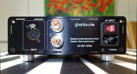
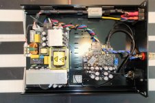
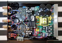
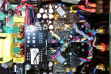
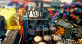
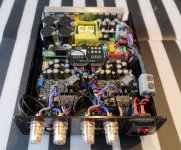
I promised pictures from my builts.
Here are a few from the internals
Note: Couldn't do more, because otherwise an error rmessage appeared "Missing security token". Don't know, what that means, but all files sizes seemed below the allowed maximum size.
Here are a few from the internals
Note: Couldn't do more, because otherwise an error rmessage appeared "Missing security token". Don't know, what that means, but all files sizes seemed below the allowed maximum size.
Attachments
Last edited:
- Status
- Not open for further replies.
- Home
- Amplifiers
- Class D
- Hypex Ncore