Hi, Having built a 10Y line preamp few years ago, I decided to work on it. Unfortunately, I didn't take any readings (HV, bias) before... Using ll1660/18mA at output (ALT-Q) and 1.5K as cathode resistor, I checked the curves but wasn't quite sure about exact operating point. Euro21 gave me some guide lines (thanks to him) and finally it crossed my mind to ask to Per Lundahl about his ll1660...This is the answer (and maybe a valuable information for some):
"For LL1660/18mA, 18mA is the operating point / working current when transformer is used in configuration "Alt S"
For the LL1660/18mA in configuration "Alt Q" the operating point / working current is 16mA
Any offset from 16mA will reduce the available AC signal, and at about 32mA the core is close to saturation."
That's correct. The 18 mA current is referred to the windings A and B with less turns (all 4 in series). As you are going to use the 2 C windings that have a bit more turns the current will be 16 mA for the same DC induction. At 16 mA the DC induction will be 0.9T and the available undistorted RMS voltage at the secondary will be 57V.Hi, Having built a 10Y line preamp few years ago, I decided to work on it. Unfortunately, I didn't take any readings (HV, bias) before... Using ll1660/18mA at output (ALT-Q) and 1.5K as cathode resistor, I checked the curves but wasn't quite sure about exact operating point. Euro21 gave me some guide lines (thanks to him) and finally it crossed my mind to ask to Per Lundahl about his ll1660...This is the answer (and maybe a valuable information for some):
"For LL1660/18mA, 18mA is the operating point / working current when transformer is used in configuration "Alt S"
For the LL1660/18mA in configuration "Alt Q" the operating point / working current is 16mA
Any offset from 16mA will reduce the available AC signal, and at about 32mA the core is close to saturation."
However, as you are going to use it as a preamp-output transformer I really doubt you will need 57V RMS output. So you can increase the anode current up to 20-22 mA. Still plenty of headroom for a preamplifier. You can try. It would be better if you can measure THD. In such case you might be able to go up to 25 mA DC current and check the distortion is low down to 20Hz at the output level you want.
The other option is to use 16-18mA anode current. With 100H primary inductance, the 10/10Y can be surprisingly linear and doesn't need to run at higher current.
Last edited:
Here are some real curves measured by Ale:
10Y | Bartola Valves
For example you can use 288V supply voltage and 820R cathode resistor. This way the 10Y will work at about 250V anode voltage and 18.5 mA (-15V bias).
In other words, once you apply 288V supply and use 820R cathode resistor: 250V those 288V will be the anode voltage, 15 V will be the cathode bias and 23V the voltage drop across the primary (1250 ohms).
Here are some real curves measured by Ale:
10Y | Bartola Valves
For example you can use 288V supply voltage and 820R cathode resistor. This way the 10Y will work at about 250V anode voltage and 18.5 mA (-15V bias).
In other words, once you apply 288V supply and use 820R cathode resistor: 250V those 288V will be the anode voltage, 15 V will be the cathode bias and 23V the voltage drop across the primary (1250 ohms).
Thanks for all informations. As I can see, you know very well that transformer. Also, there is more than one option here and a larger margin than expected... I remember having an operating point over 300V biased less than -25V (with my 1500R). However I didn't experiment at lower voltage. Unfortunately, I don't have any equipment for measuring THD and will have to rely on others experience and...My ears! 😀
If you use 10Y with this -relatively- low (16-20mA) current, and inductive load, the low (200-300V) anode voltage is not optimal. The curves there are crooked, thus THD is higher.
I prefer higher voltage, for example about 400V, -30V bias, 20mA operating point, and 10k or greater load.
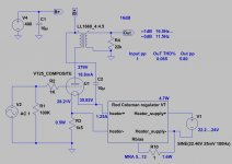
sample schematic:
I prefer higher voltage, for example about 400V, -30V bias, 20mA operating point, and 10k or greater load.
sample schematic:
Attachments
If you use 10Y with this -relatively- low (16-20mA) current, and inductive load, the low (200-300V) anode voltage is not optimal. The curves there are crooked, thus THD is higher.
I prefer higher voltage, for example about 400V, -30V bias, 20mA operating point, and 10k or greater load.
sample schematic:
Thanks for the schematic. But why did you wired the ll1660 as ALT-S ? Also, you put 1k for grid stopper. Did you experiment oscillations with those tubes?
I have parameters (parasitic C and L) only for ALT-S configuration.But why did you wired the ll1660 as ALT-S ?
Those DHT tubes (10/801/841) -which I use- are made for /radio/ transmission, so operating bandwith is very high. I automatically use grid stopper.Also, you put 1k for grid stopper. Did you experiment oscillations with those tubes?
If you use 10Y with this -relatively- low (16-20mA) current, and inductive load, the low (200-300V) anode voltage is not optimal. The curves there are crooked, thus THD is higher.
I prefer higher voltage, for example about 400V, -30V bias, 20mA operating point, and 10k or greater load.
sample schematic:
I cannot see how a 10Y run at 20 mA can be more linear at 400V than 250-300V. A new law of physics?
Thanks for all informations. As I can see, you know very well that transformer. Also, there is more than one option here and a larger margin than expected... I remember having an operating point over 300V biased less than -25V (with my 1500R). However I didn't experiment at lower voltage. Unfortunately, I don't have any equipment for measuring THD and will have to rely on others experience and...My ears! 😀
25V bias into 1500R is 16.7 mA. Having 300V anode voltage I think it will be a bit less linear than 250V 18.5 mA. However, as the 10Y is very linear, the difference should not be much. The real difference is that in my example you need 300V total supply (including voltage drops in the power supply) while here you will need some 360V. In the former case you can use cheap but quality 350V caps, for example.
As I said, being a preamplifier you will not need the headroom specified in the datasheet (i.e. 57V RMS) so you can run @20mA quite happily.
But why did you wired the ll1660 as ALT-S ?
Using the ALT Q connection, with 4.5:1 step down you won't get much gain. It will be somewhere between 3 dB and unity, depending on the operative conditions. However with some 350R Zout and low distortion it's even better than a unity buffer! You will be able to drive power amps using step-up input transformers (for example 600R:10K) without worrying about input capacitance. So you almost re-gain the voltage and have the possibility to achieve high noise rejection. Step-up and step-down transformers usually have much better frequency response. Generally with 1:1 ratio or so, except for some special designs (not the Lundahls for sure), usually you need some compensation network to avoid peaking (which doesn't sound as good as an unloaded secondary. Try this out!) and high frequency roll-off happens earlier unless you use high source impedance.
In fact the LL1660 in ALT-S will have give good high frequency response only with some 14K source impedance. But this will compromise a bit the low frequency behavior. If substantially lower source impedance you might likely get peaking and worse roll-off. With ALT-Q you don't need to worry about this and don't need to run measurements or simulations....
Last edited:
Yes I knew Zout would be low with ALT-Q. That's why I didn't try anything else. Actually with AVC (from D Slagle) at output, I didn't have any problem with gain (with both my SS and Tube Amps). But I'm going to try a stepped attenuator at input (since those AVCs are on my 01A preamp now). I'll see if there is a big difference...
You're right, I was wrong (I poorly remembered the curves). Physics is working as usual. 🙂I cannot see how a 10Y run at 20 mA can be more linear at 400V than 250-300V. A new law of physics?
it seems this tube needs lots of volts and high impedance to shine. Peter´s lab: STAX 2A3 SE amplifier, part 2
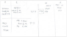
measured my pair of 1660/18 the results: (20hz,10k,100khz lc bridge hioki)
i use them as 2,25/4
measured my pair of 1660/18 the results: (20hz,10k,100khz lc bridge hioki)
i use them as 2,25/4
Attachments
it seems this tube needs lots of volts and high impedance to shine. Peter´s lab: STAX 2A3 SE amplifier, part 2
Of course it does, that is not a line preamplifier. It is a small power amplifier to drive Stax headphones.
Sorry i meant 5k ra, which if used around <300v creates extra complication like a2 mode. +extra distortion
But in hi voltage, hi impedance mode kills 2a3 easily 🙂
worth ??? VT62 801 Hytron Vintage Valve Tube LC33 | eBay
But in hi voltage, hi impedance mode kills 2a3 easily 🙂
worth ??? VT62 801 Hytron Vintage Valve Tube LC33 | eBay
Sorry i meant 5k ra, which if used around <300v creates extra complication like a2 mode. +extra distortion
But in hi voltage, hi impedance mode kills 2a3 easily 🙂
We are talking about a line preamplifier. You have -15V bias and the gain of the 10Y with some 12K load (600R load at the secondary) will be about 5.6. The transformer is 4.5:1 so it is a bit better than a unity gain buffer. In a worst case scenario you have at least 5 Vrms output before any grid current will appear. If the valve is good it will be some 8-9 Vrms (approx. 9-10V peak on the grid of the 10Y). That is enough for driving a power amp or not ??? Of course even for 5 Vrms output you have to max the volume and the source has to have 4 Vrms output! Do you know a standard source with such high output? That's why I told Crazyfrog to use a step-up transformer in the power amp, unless his power amp is already hi-gain or he has a special source with high output.
Last edited:
- Status
- Not open for further replies.
- Home
- Amplifiers
- Tubes / Valves
- About LL1660/18mA