250lbs is definitely impractical, even by my standards.
Wikipedia claimed OPT-less on Circlotron, reading the link now.
I understand impedance, thanks for clarifying.
Sreten I appreciate your candor. Please don't fall into the oh so common forum paradigm of assuming a person who is not technically proficient in whatever particular field the forum targets is generally incompetent.
IF you continuously try new things you'll find yourself a perpetual amateur in some discipline. None of that takes away what you already know.
What would you have me build with tubes which is safe? Starved plates?
I'll learn more trying to build a monstrosity than copying Fender's 5E3 circuit with Digikey $$$ or a kit off epay.
I'm easily bored. Or is that board? 🙄
OK consider this project dialed down to 200w or whatever. Is that technical enough? (really pending the outcome of reading about Circlotrons )
Wikipedia claimed OPT-less on Circlotron, reading the link now.
I understand impedance, thanks for clarifying.
Sreten I appreciate your candor. Please don't fall into the oh so common forum paradigm of assuming a person who is not technically proficient in whatever particular field the forum targets is generally incompetent.
IF you continuously try new things you'll find yourself a perpetual amateur in some discipline. None of that takes away what you already know.
What would you have me build with tubes which is safe? Starved plates?
I'll learn more trying to build a monstrosity than copying Fender's 5E3 circuit with Digikey $$$
or a kit off epay. I'm easily bored. Or is that board? 🙄
OK consider this project dialed down to 200w or whatever. Is that technical enough? (really pending the outcome of reading about Circlotrons )
Last edited:
Circlotron CAN be output transformerless, but it is not really connected with that. The transformer, when used with the Circlotron configuration, still does the impedance conversion. If you don't need the impedance conversion, then it can be OT-less.
The advantage of the Circlotron configuration is that it requires half the turns on the primary of the OT compared to other (usual) P-P approaches. So it is a good fit with using industrial xfmrs for an OT. It's also a good approach for building a notably high bandwidth OT.
Some OT-less approaches:
HF Impedance Converter.
David Berning has a patent (about to expire) on this approach, which uses a small ferrite OT with a high frequency carrier to perform the impedance conversion. (impedance: ratio of voltage to current) Similar to switch-mode power supplies. Can be light weight, but is complex and requires good test equipment. A simple mental model: a DC to HV DC switchmode converter with a tube load across its HV output gets used like a black box. Whatever current the tube draws, shows up as higher current (with lower V variation) at the input side of the DC to DC converter. You just wire the whole thing in (using the LV/Hi current input) as if it were a high current tube.
Simple minded, fool-proof, Impedance Converter.
This is what I mentioned earlier. Uses a tube and SS device hybrid combo, in a local feedback combination, to emulate a high current triode. Typically Darlington or Sziklai pair configuration, with feedback to the tube plate or screen grid to get triode characteristics for the combo. Somewhat complex also, but not nearly as complex as the HF converter. (no HF or isolation issues) Does require a multitude of power supplies however. Can be efficient like SS.
Tube-O-philes, with vacuum circulating in their blood, will of course dis-like these approaches. They would rather wire 30 big tubes in parallel to get the required current to drive the speaker directly. And move above the Artic Circle.
Last edited:
Sreten I appreciate your candor. Please don't fall into the oh so common forum
paradigm of assuming a person who is not technically proficient in whatever
particular field the forum targets is generally incompetent.
Hi,
I appreciate a brilliant engineer could build the worlds best steam
powered racing car, but I would suggest its not a very useful idea.
Competence in one area does not lead to competence in another,
and one can only comment on the ideas given for a particular area.
There is absolutely no point at all to a 500W valve subwoofer amplifier.
But if you want do it, by all means do it. We will be impressed just as
much (perhaps not) as with the fantastic steam powered racing car.
Fact is an engineering challenge is one thing, pretty pointless another.
rgds, sreten.
Check out the "M-125" monoblock amp.
tubes4hifi amplifier KITs page
Power output (4 X KT88) 125 watts.
tubes4hifi amplifier KITs page
Power output (4 X KT88) 125 watts.
If you already have some 17 Lb tube organ power transformers, the first thing to do would be to measure what voltages they put out. This will focus the hunt to what tubes are fitting.
Organ OTs would also focus the search. They can be measured by putting some AC voltage on the primary and measuring the AC voltage on the secondary. The voltage ratio squared gives the impedance ratio. Knowing what speakers (impedance) were attached then sets the primary Z. The size or weight can ball-park the Watts capability.
-------------
M-125 $1778 without tubes. Ouch!!
You should be able to build a decent 100 Watt amp for a few hundred $ using the low cost approaches, like in the DCPP Amp thread: ( a nice case though will cost more)
http://www.diyaudio.com/forums/tubes-valves/151206-posted-new-p-p-power-amp-design.html
Last edited:
Hi,
Competence in one area does not lead to competence in another,
and one can only comment on the ideas given for a particular area.
Quite the contrary my good man. So much can be learned from a mature technology in one particular application and carried into another application.
Certainly fluid dynamics is not exclusively applicable to steam racecars 😕
That being said, I sincerely doubt you'd be impressed by anything and thus ends our discourse. Cheers!
SmokingAmp speaking of Tube-O-Philes what is the obsession people have with declaring tubes to contain lethal voltage then building unshielded, unenclosed amps? The first time I saw one of them with all the tubes perched up there I cringed! Eeek 😱 and put my hands in my pockets LOL

Had a run in with a Jacob's ladder once.....
 (oof not to mention the crazy electric fencer we had when I was a kid, it'd knock you down and leave bruises)
I'd rather enclose my builds in a cage at least. Probably already in pitchfork territory

Better if they save money for 30 redonkulously conventional audio tubes 😉
813 tubes are surprisingly cheap NOS. A few $ more than 6v6, 6L6, amazing.
OOPS, we crossed posts.
Thank you for the test procedure.
I'll check them tomorrow, one IIRC makes about 550v no load.
Most of the OPT are smallish, only running a pair of 6V6, 7591 etc. I do have a larger amp but don't really want to mutilate it. (not my thread) http://www.organforum.com/forums/sh...hr40-amp-with-custom-abomination-leslie/page2
I'd been planning to make guitar, vocals, etc 15-17w amps with most of the components from others. A0-29 is almost a dead ringer for the 5E3 shopping list 🙂
EDIT $1788 um.... no....
Last edited:
100-125 watts it achievable with a tube amp. It's expensive due to the big iron, but George (Tubelab on this site) does it routinely, although he does have 50 years of experience. Anything more gets exponentially more difficult, and has very diminishing returns. You would be FAR better served with using a more efficient subwoofer or a series / parallel combination of subs to get higher efficiency. Even multiple smaller amps driving one speaker each would be better, albiet more difficult to match to each other. The four sub Infinite Baffle I'm working on is thrillingly loud with only a few watts.
Yeah, I know the absurdity of some DIY tube amps. We are used to breadboarding the fool things with wires hanging out everywhere. So much concentration is spent on the technical details of getting it to work, that we forget about the family pet or whoever wandering in. This then evolves into plate capped tubes being the "real stuff", versus uncapped tubes are for wimps. I'll still take the un-capped tubes if they aren't too expensive. (the $5 6HJ5 has no cap)
The 813 tube is a nice big beautiful tube, and it brings up another absurd facet of many DIY tube amps. So many tube amps are developed primarily for the visual WOW factor, and not practicality or safety. The 813, like most big transmitting tubes, requires lethal KV HV to operate, and has a plate cap to advertise that. The HV B+ required with such tubes requires obscene $$ to be spent on the HV power supply and OT (all custom).
The OT is particularly hard to get sufficiently functional with the high number of primary turns required to operate at such HV or Hi Z. The more turns, the less the bandwidth. Voltage breakdown becomes a big factor too. Custom winding and often multiple re-winds really drive the cost up, especially with all the special techniques used for the OT, like special magnetic alloy or toroids/C-cores, high winding interleaves, even silver wire. Getting the speaker damping factor reasonable is another issue. After spending so much on the parts, the case had better be expensive too. (the real cost driver for most amplifier products) And then there is the efficiency and heat factor.
Well, how practical is a Maserati? You can't even carry a kayak on one. Lucky to make it to the next gas station even. Useless, $$$$ advertising.
Last edited:
I'm gonna put one of these on the front LOL.

What's always missing from these placards is the smoking prostrate victim.
Worse yet someone asked me if the tubes on another amp were plasma globes and I'm pretty sure they wanted to touch one !!! (of course they didn't say plasma globe LOL)
How closely matched can two p-p channels be?
Are they close enough for each to run one of two voice coils on a dvc type speaker?
What's always missing from these placards is the smoking prostrate victim.
Worse yet someone asked me if the tubes on another amp were plasma globes and I'm pretty sure they wanted to touch one !!!
(of course they didn't say plasma globe LOL)An externally hosted image should be here but it was not working when we last tested it.
How closely matched can two p-p channels be?
Are they close enough for each to run one of two voice coils on a dvc type speaker?
Last edited:
An all tube switching amplifier (class d) would certainly be interesting. Being as its a subwoofer, your fs could be pretty low. Still need iron, though.
Nobody is building anything here, this is just idle chit chat to fill some boring hours getting other idle bored people to talk.
Me?
just woke up to pee in the middle of the night, found this nonsense and after quietly laughing a little am going back to sleep.
Bye bye Bunnies 😉

Me?
just woke up to pee in the middle of the night, found this nonsense and after quietly laughing a little am going back to sleep.
Bye bye Bunnies 😉
EDIT let's just imagine I drooled on my shirt for minute here....your fs could be pretty low. Still need iron, though.
The love here is like cold peanut butter.... tear the bread ... man I tell you what.... 😀Is this a joke?
That Hammond # yields some good search results.If you are still serious about this, you can PM es345, he designed and built 300W tube bass amps using off-the-shelf componenets, you will need two of them, one for each voice coil.
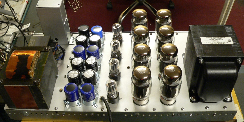
Here is another one built by claudiomas using Hammond 1650W OPT (based on the GEC design):
I am still serious. Normal just isn't my thing. (the other people have that covered)
The biggest part of patient Ebay shopping involves knowing what to look for.
As for weight ... why are people obsessed with a few extra lbs?
Put some wheels on it.

Last edited:
Fs in my description is the oscillator frequency for the switch mode amp, not the speaker itself. Given the small bandwidth requirements for a sub amp and the natural low pass of the driver, one could use a much lower switching frequency. Something that a tube might be better able to handle.
Anyhow, that's zeroth order stuff for a class d amp. And you still need a bunch of iron in the output transformer.
Good luck.
Anyhow, that's zeroth order stuff for a class d amp. And you still need a bunch of iron in the output transformer.
Good luck.
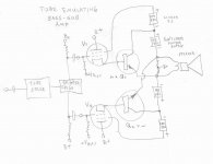
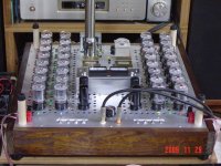
As a practical approach, I would go with something like this approach.
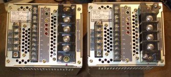
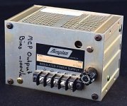
Tube/Darlington outputs emulate high current triodes in P-P. A Circlotron circuit is used without any OT. Main power supplies are 4 lb Kepco RCW48-7.5 switchers. Some Acopian linear supplies for the 100V and B+ ( 250V). Amplifier cost about $300. (not including the case and big heatsinks) Weight about 20 lb.
(maybe 30 lb with big heatsinks)
Bipolar transistors would likely be 3 or 4 paralleled with emitter degeneration resistors to reach 500 Watt safely. Something with near constant Beta. Similar P and N type available.
High gm tubes for V1 and V2 will keep the output impedance low. Could put a global N Fdbk loop back to the input stage too. (for high damping factor)
Unfortunately it's NOT going to look like this:
http://www.diyaudio.com/forums/tubes-valves/213260-808-se-build-3.html#post4674360
Or like the last OTL pic attached. So maybe put some of those plasma globes on top of the chassis. Then glue some huge plate cap coolers to the globes and run dummy wires to them. Can DARE people to touch them like you can.
Attachments
Last edited:
Woops, minor correction to the above.
The bipolar transistors Q1 and Q2 are both NPN type, no need for complementary P type. (an advantage of the Circlotron configuration)
Some additional details:
Individual bias servos for Q1 and Q2 idle currents would be needed. (Standard class AB capable Op Amp servo for each: A low freq. integrator and V input limiting at 2X the desired idle drop across the emitter resistors to ignore class B excursions.)
A global LPF DC Neg. Fdbk loop would keep the output idle voltage of the amp at zero Volts. (or combined LPF DC and AC for a standard SS global N Fdbk loop.)
Big honking electrolytics would be needed across the main 48 VDC supplies to handle signal peak currents. (1000 Watt peaks into 2 Ohms for 500 Watt average output. The RCW48-7.5 supplies are rated 360 Watt continuous, each. So the amp could theoretically handle 720 Watts sine wave continuous in class B.)
Last edited:
@ jazbo8
The link you gave in Post # 4 i've seen before, & worth viewing if people haven't already. A monster of an amp 😀 Clever guy who's been around for years, but it seems he hasn't updated his www for some time 🙁
The link you gave in Post # 4 i've seen before, & worth viewing if people haven't already. A monster of an amp 😀 Clever guy who's been around for years, but it seems he hasn't updated his www for some time 🙁
Perhaps he retired? Now that I think of it, that's an advanced project, probably not really suitable for a newb like the OP.
There have been more than one of these 1000V to 2500V B+ type amplifiers where the thread suddenly goes silent. Not a good sign.
Parts Express sells a 200W speaker line matching transformer for about $60. With a primary side impedance of 25R, this thing offers an attractive fix for the major drawbacks of tube OTL power amps. The necessary supply rails of +/- 150V or so and power tubes capable of 4A peaks are not terribly challenging requirements. And perhaps it's worth mentioning that an audio transformer of this type should be about the simplest DIY iron project imaginable.
- Status
- Not open for further replies.
- Home
- Amplifiers
- Tubes / Valves
- Newb seeks to drive DVC 4+4 ohm 500w RMS subwoofer with tubes.