http://oi65.tinypic.com/2m2c0tt.jpg
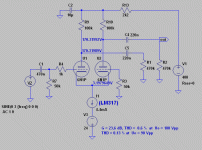
the simulation would give approximately thd(1khz) 0.06 % per outputs
(of course i can improve constant current generator,i wanted it to be simple)
the simulation would give approximately thd(1khz) 0.06 % per outputs
(of course i can improve constant current generator,i wanted it to be simple)
That is a good value. However, if 35 Vpp is what is needed in actual amplifier, then I would check that the phase splitter is capable of supplying at least 70 Vpp without excessive THD rise.
I have used basically similar circuit, but with 6N1P-EV and 6DJ8 and LM317 as the CCS, since it is very simple and only a few components are needed.
I have used basically similar circuit, but with 6N1P-EV and 6DJ8 and LM317 as the CCS, since it is very simple and only a few components are needed.
Last edited:
Phase Splitter
Hi,
Your circuit was interesting, so I ran a simulation in LTSpice, and I did not get the same values as you. To get the same current in the tubes I had to adjust the resistors in the ccs. My values for distortion, and Vout is different from yours, see attached pdf file. I got 30 p-p out for 1 v p-p in. And about -49db THD, which gives about 0.35%. If you look at the fft from the simulation, 3d harmonic distortion is the largest, at 30 v p-p out.
Tried with 12ax7 model to check, gave about the same figures.
But off course it's only simulation.
Attachments
Last edited:
Single-BJT CSS isn't that good, use depleted mode mosfet, IXYS 10M45S or LM317.
I run simulation in LTSpice and found single-BJT CSS useless.
Prototyping (albeit different schematics) shown that LTSpice is very accurate in THD analysis.
Hope this helps.
I run simulation in LTSpice and found single-BJT CSS useless.
Prototyping (albeit different schematics) shown that LTSpice is very accurate in THD analysis.
Hope this helps.
The simulation result depens a lot on the used tube model.
But below is one I have used and the actual performance is very close to simulated one.
Yes fine, but only way to extract full performance is to feed into Williamson diff drivers or straight into a low Pout class A op/stage; Morgan Jones did the working out for the Mullard 5-20 and found the long tailed quite heavily loaded esp when the op/stage grid leak resistor values is reduced, then it starts to produce more thd and also by Miller effect. Fussy with distortion ? Look at the big picture with the whole design; wrap it up with copious amounts of global NFB. That's exactly what many early designs did.
rich
The grid resistors will be smaller depending of tubes selected unless a williamson type driver tube is used.Yes fine, but only way to extract full performance is to feed into Williamson diff drivers or straight into a low Pout class A op/stage; Morgan Jones did the working out for the Mullard 5-20 and found the long tailed quite heavily loaded esp when the op/stage grid leak resistor values is reduced, then it starts to produce more thd and also by Miller effect. Fussy with distortion ? Look at the big picture with the whole design; wrap it up with copious amounts of global NFB. That's exactly what many early designs did.
rich
With 6550 or kt120 it should be 50k.
The grid resistors will be smaller depending of tubes selected unless a williamson type driver tube is used.
With 6550 or kt120 it should be 50k.
The 6550 is a nasty tube for that...Those with simulation programs should load the long tail o/p's with those 50K grid leak values plus 120pF in shunt (Miller effect) and see the results with rising frequency.
This is an example where the op tube actually governs the driver !!
rich
http://www.diyaudio.com/forums/atta...hase-splitter-low-distortion-6n1p_ccs_ltp.gif
R3 smallest possible value, bode diagram will look better
(U2 anode grid capacity will impact less)
would be interested to see bode diagram when R3 = 50k vs R3 = 1K.
R3 smallest possible value, bode diagram will look better
(U2 anode grid capacity will impact less)
would be interested to see bode diagram when R3 = 50k vs R3 = 1K.
Last edited:
Have you read this article?
Denk mal wieder!
It's improved phase splitter. Attached is the translated English version of which I corrected some of translations. In addition I'm interested in harmonics of dissimilar tubes in triode mode as well. I'll try to sim, if anyone has sim or going to sim, please share the result of simulations (loaded & unloaded).
Attachments
Last edited:
While the Schlange article is interesting, why not read the original Bailey article in English instead?! New Phase Inverter
In particlar read Roddam's comment on the tubes used.
- Status
- Not open for further replies.
- Home
- Amplifiers
- Tubes / Valves
- phase splitter with low distortion
