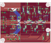
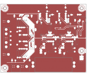
would splitting the ground plane on a PCB into 3 sections that are still commonly connected be a bad idea.
my idea is to split (shield) the power from the main board so there is no direct (line of sight connection) and at the same time split the input and output audio sections as well. all three planes are still connected at the top of the board i'm just making it so there is no direct connection so each section has to travel to the common ground but not interfere with each other.
my idea is to split (shield) the power from the main board so there is no direct (line of sight connection) and at the same time split the input and output audio sections as well. all three planes are still connected at the top of the board i'm just making it so there is no direct connection so each section has to travel to the common ground but not interfere with each other.
would splitting the ground plane on a PCB into 3 sections that are still commonly connected be a bad idea.
Can you post the schematic? It may work.
its not included on the schematic, i have used 'tRestrict' in eagle to do the splitting.
It may work ok, but it's hard to tell without a schematic.
the common is the connection between the bridge rectifiers '+ com -'.
One important point is to avoid coupling the current pulses going through
the capacitors after the rectification diodes, into the audio ground.
What is it you are trying to accomplish? Sometimes a fix in search of a problem can induce trouble.
Mike
Mike
there are only 2 1000u coupling caps right at the top of the board. the regulation is RJM's x-reg (with kind permission). the bridge rectifiers are dip4 50v 1.5a and on board.
i'm trying to accomplish making sure that each section does not interfere with each other and hopefully give a cleaner ground plane for each section.
i'm trying to accomplish making sure that each section does not interfere with each other and hopefully give a cleaner ground plane for each section.
i'm trying to accomplish making sure that each section does not interfere with each other
and hopefully give a cleaner ground plane for each section.
Can you repost the board, deleting all copper plane areas other than ground?
here ya go.
The voltage regulator circuit will likely couple noise to the rails with this layout,
since the op amp and resistors won't have a quiet ground. I'd separate the rectifiers
and their DC smoothing capacitors into a power plane that is separate from all other grounds.
When that is done, all the regulator and audio grounds can then share the same ground plane.
This audio ground plane should connect to the power plane at a point brought out as a stub
from midway between the input electrolytics' ground leads. Also keep each rectifier and
filter capacitor pair close together.
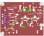
if i'm reading this right... box in the caps and rectifiers with a connection to COM then take a bridge to from the box in the middle to the main ground plane?
i'll draw something up.
i'll draw something up.
something like this, green line is split box, blue line is stub.
That's more like it, and flip the rectifier filter caps so the grounds are nearer the audio circuit.
Keep both of the rectifier grounds on the power plane, that's important.
In fact, I'd consider swapping the relative positions of the rectifier and filter capacitor,
so the capacitor grounds are next to the stub.
Last edited:
thanks rayma, i'll also see if i can get the caps a bit closer as i can move things about up there a bit. i'll play with it tomorrow but for now my bed is calling.
thanks rayma, i'll also see if i can get the caps a bit closer as i can move things
about up there a bit. i'll play with it tomorrow but for now my bed is calling.
Me too.
Split the grounds into input, output and power. Connect the input to output and the output to power.
Try not to overlap the input GND with the supplies or run the input traces over the power GND.
Try not to overlap the input GND with the supplies or run the input traces over the power GND.
A good place for inspiration is the my_ref-fe.
Input ground plane over the input traces. Power ground plane under the power traces. No power traces running over the input ground plane.
http://www.diyaudio.com/forums/group-buys/229358-my_ref-fremen-edition-interest-group-buy.html#post3356205
Input ground plane over the input traces. Power ground plane under the power traces. No power traces running over the input ground plane.
http://www.diyaudio.com/forums/group-buys/229358-my_ref-fremen-edition-interest-group-buy.html#post3356205
i had a good look at that but i'm little confused.
the ground planes look like they are for each stage. the input is on 0v which to me says that it relies on the input source ground which is no bad thing as it removed the duty on the rest of the circuit except that if the input source has a bad output grounding scheme (mostly very unlikely) then so does the input. i like this idea.
the input voltage ground is tied into what looks like a relay to feed the output ground to COM at switch on for 'anti rush in/thump control'.
- Status
- Not open for further replies.
- Home
- Amplifiers
- Headphone Systems
- splitting ground planes


