Reactance:
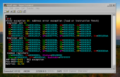
For real-time debug, the simplicity of classic TERM software and RS-232 is hard to beat. Usual methods like JTAG are a big fail for real-time because briefly halting MCU or periperals screws up a SMPS or any real-time application. Colors help to make it more emotionally friendly, like an exception dump in color. The most effective way to test real-time code is to watch all the variables in computer screen.
https://youtu.be/v-BIMoAGM5Q
Choco:
Optimum methods are universal. If you are doing it right you will need the same MCU features as anyone else, neighbors and people living in the antipodes will reach same result over time. Physics is not property of anyone. Too bad the lack of connection with nature, bootstrapping is surely taking place. Many many interesting biologic features have to be dropped to reach this reasoning, Mr. Droid.
Attachments
Using ANSI color codes in a serial terminal, that's smart. Gonna steal that idea.
Sent from my Nexus 4 using Tapatalk
Sent from my Nexus 4 using Tapatalk
Reactance:
For real-time debug, the simplicity of classic TERM software and RS-232 is hard to beat. Usual methods like JTAG are a big fail for real-time because briefly halting MCU or periperals screws up a SMPS or any real-time application. Colors help to make it more emotionally friendly, like an exception dump in color. The most effective way to test real-time code is to watch all the variables in computer screen.
https://youtu.be/v-BIMoAGM5Q
Thanks, I did something similar PIC`s have two USARTs one can be used as a debugging port (variable dump) the other for comms line for rx/tx control. but this should also cause a delay in execution.
I noticed you have a split screen left shows basic and right looks like a translation (human brute force) to assembly. 😀
Last edited:
Dear Ms. Droid,
this form of 'watching a digi-scope' is something I still have to learn.
😎
Is this your 'bootstrapping drug'? 😀
this form of 'watching a digi-scope' is something I still have to learn.
😎
Is this your 'bootstrapping drug'? 😀
😱 Already screening 5 parameters is starting to become tough, but something like 40 simultanously?! 😱
Typically I can do at max one thing at the same time.
What do I need consume to manage 40 in parallel?
Or am I simply of the wrong sex?
Typically I can do at max one thing at the same time.
What do I need consume to manage 40 in parallel?
Or am I simply of the wrong sex?
😱 Already screening 5 parameters is starting to become tough, but something like 40 simultanously?! 😱
Typically I can do at max one thing at the same time.
What do I need consume to manage 40 in parallel?
Or am I simply of the wrong sex?
I am going to have a go at this even in its obfuscated form.
1) The attached pic shows 40 registers, its a memory dump similar to a windows crash report only its real time.
2) The video shows the most interesting part, a digital V Loop, with parameter lookups for the various control blocks, and what looks, like IIR filters, supervisory state for temperature, maybe OV/OC trips, retry failure count and other things like power line cycle count (frequency monitor)?
"Please don't get me wrong, for multiple reasons I am not voting for exzessively small caps, but it is worth to spend some efforts in loop control and catching the demand of lower frequency contents of the music signal with the power electronics, not with the caps.
For reference I am attaching a load step measurement of one of my early DIY PSU designs.
It was a trade off and had significant amount of output caps. In fact 2x3300uF at +/-59V for a max. power of 1400W for 10s and continuosly allowing a 33% load duty cycle with 1kW.
In case of a 1kW load step the output voltage drops just 0.7%, with an undershoot of just 0.2% for roughly 300us. Stepping back to zero load results in a blameless 200us slope.
At the same time this design can compensate an input voltage drop to approx. 50% of its nominal value. For such a behavior already a simple linear first order control loop does the job.
For comparison: Catching the low frequencies by the caps with just 0.7% voltage drop would ask for approximately 2x 250 000 uF instead of 2x 3300uF. Reducing cap size almost by factor 100 with just moderate efforts in the power electronics and very low efforts in the control loop - that's worth it and usually will overrule some few single % difference in efficacy.
The screen shot is showing multiple load steps between zero load and 1kW.
White trace is the +59V rail, measurement DC coupled: 20V / Grid
Red trace is the AC component of +59V rail: 200mV / Grid
Time base: 1ms / Grid"
choco: I see that your approach is entirely different. Anyway, the fast PSU response you have, can only be implemented into the dc dc converter. To then cover the energy step demand at the 400V primary bus, and trying to still meet some decent power factor, the PFC must be slowly voltage regulated and again good storage (450V caps) is needed.
I am not talking 0.7% drop at the secondary DC rail. Look at UCD2K for example: They sell it as 2KW at 4Ohm module. It is a full bridge. Give it a nice 185VDC rail, and you can watch the rail sagging down to about 130VDC, while the 2KW output power demand is higher than what the PSU is at all able to deliver. The higher the storage, the longer the bursts can be before finally - of course - the instant power demand must decrease or the PSU must be able to deliver more and told by the regulator loop to wake up. If the power demand is less long in duration or less high, then the PSU has an easy cheesy life, considered that typical music signals have low average power but short high peaks that must not be truncated / clipped.
With that "sagging" approach you can support very high transient peaks (in this case 4kW for extremely short durations), medium bursts 2KW for a little longer durations and lighter PSU overloads (e. g. 1000W with a PSU that can only do 750W e. g.) for many milliseconds, just as they are occurring in real signals. Highest pulses very short, medium pulses longer on average.
On the other side, support the UCD 2K with a very fast regulated PSU, few storage at a rail 135VDC, and you still can support 2KW with a beefy fast regulated PSU, maybe even continuously, good, but you completely loose the ability to deliver higher power bursts.
Summary: If the music is highly compressed and contains long sine waves at full power at so low frequencies that the double frequency power demand cannot practically be "averaged out" by storage anyway, then maybe your approach is even better. For typical music signals I d still stick to my approach.
gmarsh:
The TERM/ANSI debug idea is so old that "remembering" would be more adequate than "stealing". If someone into analog electronics wanted to get into digital processing they should study the history of computing and its methods, and then choose an IDE. Executives seek computing into a fancy envelope and with a lace, and this is what is sold to them, but optimum computing and electronics are inherently "dirty" and heuristic in some aspects, like biology. Optimum is inherently excluded from their options as a result of their phobias haha
Choco:
If you can do at max one thing at the same time, technically "you" is just a non-privileged thread running into a much bigger "you" multi-core cell computing system. Go figure out what is the operating system, who are the system administrators, and how many other stealth "you" threads they have running.
Of course, predictable-result programming practices dictate that an strategic order must be followed when validating functions and loops, so there is no problem in dumping all variables in the same screen, because any programmer obtaining predictable results will know in which order and conditions the variables have to be checked. You are sounding like a programmer not obtaining predictable results, or maybe predictable results depending on external unknown validation strategies? Be careful with bugs haha
Same applies for watching scope and validating electronic circuits.
Last edited:
ANSI color reminds me of dialing into BBSes when I was younger, when BBSes were colorful things full of ANSI art, ANSI door games and all that.gmarsh:
The TERM/ANSI debug idea is so old that "remembering" would be more adequate than "stealing". If someone into analog electronics wanted to get into digital processing they should study the history of computing and its methods, and then choose an IDE. Executives seek computing into a fancy envelope and with a lace, and this is what is sold to them, but optimum computing and electronics are inherently "dirty" and heuristic in some aspects, like biology. Optimum is inherently excluded from their options as a result of their phobias haha
Then the internet happened, I gave up on BBSes and go into IRC/Usenet/whatever. ANSI underpins pretty much everything that runs in a terminal, but unixland isn't exactly a colorful place - usenet, IRC, text editors, e-mail clients, etc... are all B&W. Kinda forgot about ANSI color, I guess. Thanks for the reminder 🙂
Fully agree that engineering is dirty at times. I design autonomous, battery operated receivers with DSPs where low power is paramount. There's a lot of weird tricks and compromises made on the hardware side to save power/parts, and the DSP code is an optimized-for-minimum-MIPS, largely assembly coded thing that will be very hard to maintain by someone new to DSP. Any time you're chasing targets like that, things get ugly.
Its the targets that make the design - the role of constraints in optimization is set out eloquently in Brook's book 'The design of design' - highly recommended : www.amazon.com/Design-Essays-Computer-Scientist/dp/0201362988/ref=sr_1_1?s=books&ie=UTF8&qid=1460510783&sr=1-1
Looking at STM32F334xx datasheet I see that the DAC only accepts Vref from 2.4V to 3.6V. This is enough to discard this whole family of MCUs for advanced SMPS control, because DACs accepting down to 0V reference are required for all AC<-->DC comparator-based modulator applications.
Theorem: You cannot design a optimum tool for a job if you are not already a master doing this job. If you try to design a tool for some job you do not take the effort to master first, the tool will *always* contain essential pitfalls.
abraxalito:
Thanks for the reference, looks good, this book probably discusses similar facts to the ones I'm discussing hehe
Last edited:
Seems like I should be more serious. Of course I am not concerned about the number of relevant parameters. ...and paralleling, yes - even at home in the mean time I am using two stacked four chanel Tekscopes with synchronized Triggers, in order to watch more signals at the same time........memory dump...only its real time...
...most interesting part, a digital V Loop, with parameter lookups for the various control blocks, and ...
But reading 40 HEX numbers with high refresh rate (but likely still by far to slow to picture up even a slowish 100Hz modulation, except by multisampling and hoping that things really repeat periodically and without aliasing effects) - I cannot.
Yup....the fast PSU response you have, can only be implemented into the dc dc converter....
...the PFC must be slowly voltage regulated...
Don't bother about the 0.7%, I agree usually an amp does not need this....that "sagging" approach you can support very high transient peaks..
The shown values of 3300uF are also supporting your sagging approach for higher peaks of short duration. It can be scaled to any desire (but of course needs adjustment of the loop gain).
However also the theoretic extreme with almost zero output caps but perfect regulation would need to cover just the expected max. peak power. The factor two happens within each single period of a sine wave. Compressed or not does only change how much average power and thermal capabilites are needed. In any case the peak currents can be predicted from the rail voltage and lowest load impedance including impedance dips.
Overall it is just about balancing out how much you want to cover with the caps and how much with the power electronics. Doing only the average with the power electronics and all the rest with the caps, not just one half wave but a full beat of a base drum will not just need 300000 uF but more 3F. What's wrong in using the growing capabilities of power electronics in order to operate with smaller caps, less weight and less wasting of resources?
If done right, one can get the same capabilties from both methods.
Yes ! That's me.... "you" is just a non-privileged...

Or am I just not stating that I would be the one who knows the universal optimum and will never fail?You are sounding like a programmer not obtaining predictable results
Last edited:
Looking at STM32F334xx datasheet I see that the DAC only accepts Vref from 2.4V to 3.6V. This is enough to discard this whole family of MCUs for advanced SMPS control, because DACs accepting down to 0V reference are required for all AC<-->DC comparator-based modulator applications.
Theorem: You cannot design a optimum tool for a job if you are not already a master doing this job. If you try to design a tool for some job you do not take the effort to master first, the tool will *always* contain essential pitfalls.
Things in the MCU world does not work this way (ideal) you should know this?, on-board peripherals such as DAC and ADC sections are very limited (deliberately) in capability and overall performance,heck.. some MCU manufactures (most actually) INL/DNL specifications are not even mentioned or show very shy amounts of technical information some obfuscated or hidden deep in the datasheet.
The point is if you want a capable ADC/DAC then an outboard solution is the way to go, yes it introduces part count and bumps up the cost, but that`s how "things work" when making engineering trade-offs..
Im still learning alot about ADC and DAC technology, especially how to read ADC/DAC datasheets (a task in its own right), one thing is for sure you NOT getting full peripheral flexibility from a MCU there has to be a trade-off somewhere...
In your case you using 8-bit mcu to do partial floats, do some house keeping, real-time calculations ect.. you claim you wrote a float implementation (this is good it signals your knowledge at the assembly level), but a ARM core can do this in a few instructions (some even support SIMD) where you (even at the most human optimised level) will be forced to perform few instructions for the same outcome (not matter how much you try and optimise an 8-bit system)
Last edited:
Reactance, you keep trying to criticize Eva's design and choice of parts/tools, but at the end of the day she's built and demonstrated something that works.
If you haul the PIC out of her design and poke in an ARM, what's the gain? The ARM will spend more time in idle state, and pull a few less milliwatts of power, saving a completely insignificant amount of power in a kW-output supply?
The world runs on "good enough". If the processor has the MIPS to keep up with the work it has to do, even if it's burning those MIPS emulating higher precision or floating point math, it's good enough.
Reactance, you keep trying to criticize Eva's design and choice of parts/tools, but at the end of the day she's built and demonstrated something that works.
If you haul the PIC out of her design and poke in an ARM, what's the gain? The ARM will spend more time in idle state, and pull a few less milliwatts of power, saving a completely insignificant amount of power in a kW-output supply?
The world runs on "good enough". If the processor has the MIPS to keep up with the work it has to do, even if it's burning those MIPS emulating higher precision or floating point math, it's good enough.
I'm not criticizing. you are assuming this. I cannot criticize something I didn't see, this moment in time its just a discussion. nothing more I am free to have a healthy discussion, you seem more to be the forum police. why?
Last edited:
"Doing only the average with the power electronics and all the rest with the caps, not just one half wave but a full beat of a base drum will not just need 300000 uF but more 3F. "
Also not true. we should not be talking Farads, but Joules here, Joules in relation to power and time requirements
If the bass beat is, say 70ms in length and the headphone needs 0.2Watts to produce 100dB, then the energy requirement (=difference between stored energy fully loaded and after sagging) would be 14mJ to cover the beat. Quite a tiny capacitor. If 20000 Watts is needed into many double 18 horns to cover a crowd of thousands of screaming people outside, then that same bass beat is consuming just 1400 Joules, most likely far less since the speakers consume only the real power not the apparent power. In case of 8 Amplifiers used to power the subs, that is - for example 8 pcs of 200V / 2200uF sagging from 182V to 130V per amp EVEN if the PSU is not doing anything during the beat, what is never the case. But you need 142V to still support 2500W at the very end of the beat. Easily achievable if the PSU is helping during the beat. But if that beat is ocurring 2.5 times a second, the duty is 0.175. So a decent 500W PSU could do the job. Put a 1000W in with 2500W overload capability up to 5 seconds in case the drummer goes crazy, use only 6 capacitors instead of 8 and you are good to go for the show. There is no need at all for a PSU that can deliver 5000W what is the peak output power. Of course all that power and storage requirements double if you are going to implement 2 channels into one amp house and use only 4 units for the show what is a more realistic case.
Let's stop comparing an Unimog vs a S-class. I was sticking to smallest sagging (Stability and low noise was the request of the related high end amp designer and I looked into the topic simply for a friend and for curiousity), while you are sticking huge rail sagging.
Of course an amp with reasonable PSRR and decent input voltage range and sonic requirements just for PA can live with a massively dropping rail.
And obviously, if you generally step up the voltages as in your example then this will reduce the amount of required caps further.
The two extremes would be a PSU with 500Wpeak and roughly 18 000uF or a PSU with 5000Wpeak and almost no caps.
The optimum in terms of size and weight is somewhere inbetween and you are proposing a PSU with 2500Wpeak and 12000uF.
Your power stage is just a factor 2 away from the extreme without caps, but factor 5 away from the extreme of doing all short term power with the caps.
So your choice is already power electronics instead of caps.
And also your choice is to design for less sagging than theoretically allowed. Just you are buying this with larger (but not crazy) caps instead of regulation, because this makes your system more forgiving vs unknown peak load situations. Ok for me.
Seeing your todays choice makes me even more confident that the demand of light weight @ low cost will give momentum towards less caps.
I'm not being the forum police, I'm just making a counter-argument.I'm not criticizing. you are assuming this. I cannot criticize something I didn't see, this moment in time its just a discussion. nothing more I am free to have a healthy discussion, you seem more to be the forum police. why?
Thanks for the reference, looks good, this book probably discusses similar facts to the ones I'm discussing hehe
I figured as you're talking my language here (optimization, story telling, heuristics, economics of resources) you might possibly enjoy the same books I've been reading in the past few years. Like you I'm intrigued by the optimization process in designing something - whereas most guys on DIYA seem to go for maximizing a particular parameter (a case in point in amplifiers/preamps - THD and SNR). But Goodhart's Law (from economics) says that 'A measure that becomes a target ceases to be a good measure'.
Here's another one which might tickle your interest - it focusses a lot on optimization and heuristics (I've not finished it yet, its one to dip into over time rather than read front to back) : www.amazon.com/How-Solve-Heuristics-Zbigniew-Michalewicz/dp/3540224947/ref=sr_1_4?s=books&ie=UTF8&qid=1460589377&sr=1-4
ViennaTom:
In practice, cost optimization for products made for the real world dictates choosing power capacitors by their ripple current and expected operating life. This dictates an optimum rail capacitance, high enough to make it long lasting, like 20 years, and low enough to get it in a competitive size, weight and cost. Increasing the short term power capability of power supply simply results in lower cost and smaller size and weight than growing the capacitor bank. It just requires some more R&D.
Oh, wait, but making the power supply stronger can also increase long term power capability, this is achieved by design, like assuming no fan to rate continuous power and including a fan connector at the same time. Wanna get more long term power? Add a fan. Audio power supplies should perform up to power levels above HT requirements without a fan. Quite different from computer, telecom or lighting.
As you probably know, a PFC voltage loop must provide reasonable rejection at all multiples of line frequency, and at the same time must pass components below line frequency with as little attenuation and phase shift as possible. There are various approaches for this problem, from a simple 2nd order lowpass, to custom digital filters. Again this is a matter of extra R&D and there is a theoretical maximum filter performance attainable, which results in highest capacitor cost/weight/size optimization.
Less optimal control loops need more expense in parts to compensate the lack of R&D.
Reactance:
There is probably something you are not yet understanding about the whole integrated circuit industry. Even though integrated circuits are offered as general purpose, they are designed considering the requirements of a set of applications that may be more or less suited to reality. Over time, integrated circuits gain more acceptation, or become forgotten, or promising parts end up used in washing or coffe machines, depending on how easily they match the requirements of more and more optimized circuits and evolving application fields. For example, the limitations in many current chips are not evident until trying to improve towards more optimized magnetics, like inductor+transformer in the same core and resonant soft switching. These designs represent an improvemen both in cost and efficiency, but are highly reactive and non-linear systems. Try to control them with a PID haha
I'm anticipating the obsolescence of something you are probably bidding on, that's the occurrence. New revised MCU families will be issued with time, or parts will be discontinued, that's all.
abraxalito:
Thanks for the references. That signature is also a good one haha
For optimization I make a list of all primary variables involved (weighted magnitudes and/or cost, estimating "hidden" reactive +/- costs too), another list of minimum design requirements, also I gather notes about the choices available, and then I find the option with the lowest 'overall design mismatch * cost' factor. 'Design mismatch' can be thought of as a vector or magnitudes. Sometimes the process is interactive, like finding optimum topology for existing parts, or estimating what part types are less likely to go obsolete because they are used satisfactorily in well established types of electronic equipment.
Last edited:
- Status
- Not open for further replies.
- Home
- Amplifiers
- Class D
- Some people wonders: Can class D do the power advertised?