Judging from my searches of the web I don't think I'm belaboring an old trick here, at least not exactly. I hope someone finds this useful. The cool factor is immense, but the practicality and (so far) performance are equally good.
Recently I was faced with the issue of how to modernize my sources. I had used my fairly large garage to build a stereo 4-way array of loudspeakers, reduce my signal-processing (EQ, Xover) needs to a homebuilt box housing two Minisharcs running FIR filters built from member POS' RePhase, one as a fullband EQ, the second in the 'sharc stack' as 2x4 xover. Power amps proved surprisingly easy, inexpensive class D (or AB) chip-amp boards easily being able to drive the 15" woofers and horn-loaded higher-register drivers to monstrous levels without visible (simple scope I/O comparison) or audible distortion while sounding crystal clear at all volumes. After much work, I was clearly being hampered by my heretofore-neglected sources --- an FM tuner with rabbit ears and a small CD/DVD player.
Clearly, my desktop computer was a prime candidate, but it is housed in a small office some 45 feet away. Stringing a 60' or more cable in the open was out of the question, as was routing one through the walls. Wireless seemed to be the solution, but how?
The first solution (still in operation as a backup) was the following:
1. purchase an inexpensive USB-to-SPDIF converter (of course),
2. purchase an inexpensive Tx/Rx AV pair (composite video with R/L analog audio) and use the respective video in/out to send/receive SPDIF. Direct SPDIF plugin on each end. Works like a charm.
But curiosity got the better of me (it is a hobby, after all) and I wondered why a laser couldn't send digital audio to a toslink receiver as easily as a cable. The answer again was simpler than expected after a week or three of struggling with ideas and waiting for very cheap parts (many of which alas will have to await another project, but so what). The resulting setup, working right now sending a stream of the BSO to my sharcs, was made this way:
1. purchase an SPDIF-to-toslink converter (about $12) and its counterpart toslink-to-SPDIF converter (again ~$12),
2. remove the former from its case. It contains an RCA socket, a 75 ohm termination, a transistor and a 7404-family inverter and several resistors and caps. These remain intact.
3. It also contains an integrated 3-pin optical output unit, fed the output of the inverters, a ground line and a power line. This is the only thing removed (it may be glued --- try iso alcohol).
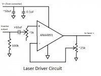
4. now the interesting part: order a small, cheap (mine were 10/$8) laser module, 5mW, 650nm. Mine are 6mm copper/gold colored with red/white pigtails. Construct a support circuit. Mine consists of a 100 kohm input-impedance shunt, a 68uF cap (for DC isolation between the boards, probably not necessary), and a resistor pair for output gain from the single-supply amp. I chose the ADA4891-1 with video GBWP. I also splurged for a small spring-loaded SOIC-to-DIP pin converter so I could handle the absurdly small op amp. It has 125mA output, easily enough to drive the small laser.
Since I had no idea what I was doing (the laser was a mystery... what were the thresholds, did it have a killer slow-turn-on protective mechanism, etc.) I used a 25k board-size pot I had on hand to act as both of my resistors (wiper to -in, one leg to output, the other to ground) and simply 'tuned' it to the best output. In my prototype's case I was using an older converter unit. It looked the same as the one used in the boxed current model superficially and generated a nice rail-to-rail (0 to ~4.3v) square wave for output to the laser. The 'beta test' boxed module's toslink converter looks identical as mentioned but it fed an inadequate 1v power to its (presumably) higher-bandwidth output module and seemed to have output grounding separate from input, unlike the other. It turned out that this was due to board damage incurred while removing the toslink diode module. It remains in use anyway as signal transmission results are indistinguishable. I sent 'real' ground and 4.2v supply voltage to my laser board. This 'beta test' model (sending the BSO as I type) outputs a 2v p-p signal with 2v DC offset to the laser.
The laser handles either input signal. Apparently it lacks any slow-turn-on protection since it modulates effectively with either 0-4v or 2-4v p-p digital signaling. About 40' away, the face of the toslink receiver is lit bright red. Hint: I found at test distance (about 1') that things worked best if the laser was not focused directly at the receiver's photodiode. Saturation? Don't know. But a strip of plain old translucent Scotch 'magic' tape stretched across the square toslink opening on the receiver solved everything, diffusing the light and also serving to widen the hot spot. It's a great beam-error corrector.
The setup is impervious to ambient light (tested today with all 32 long-tube flourescents turned on, plus a lot of sunlight, even bright LED flashlights). There is no need to modulate/demodulate the signal as on my 5.8G wireless. There is no seeming possibility of interference (unless I block the laser path with my hand). It can't interfere with my wifi. My setups have an aggregate 30 hours or so on them now, including continuous spans over 6 hours. The tiny laser's beam spreads to about 1" at distance, still plenty bright enough to excite the photodiode through the tape with minimal fussiness over beam placement. The laser sits next to the box housing the 2 boards, mounted in the alligator clip of a 'third hand' board soldering holder/magnifier. It makes laser alignment simple. It also acts as a good heat sink. It costs $5-$10. The box has an oversize banana-pin connector for the laser wires (silly but use what you've got on hand if possible, I always say). Be aware that the laser case is usually 'hot', i.e. mine shows 2.2v DC-average, about half the rail span.
The laser-sent signal (or the 5.8G AV 'backup plan' signal) are fed to a pre-sharc Ultramatch, which acts not only as a mixer of sorts but also as an indicator of signal integrity with its array of informative LEDs on the front panel. It's not absolutely necessary but it's very helpful.
Caveat: I generally send 48k/24bit SPDIF from the computer. Since the Minisharcs run a 48k plugin there's no point to using higher rates. Depending on the laser amp you choose, I believe a good deal higher is practical. The 5.8G wireless AV will send 48/24 tops. The laser is confirmed to 96/24 (as high as the Ultramatch goes).
Clearly a better job can be done with more analysis, but at this point I am waiting for operational bugs to show up so I can fix them rather than obsess about perfection (I do that enough). Some photos are attached.
Notes on attached photos:
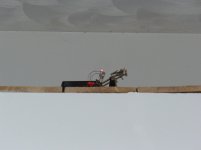
1. The 'box' on left, laser mounted on board-holder on right.
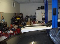
2. Shot across garage to receiver to illustrate the distance.
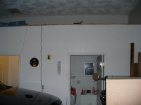
3. Laser at a distance (small thing over door; to-be-improved power wire and spdif cable at left).
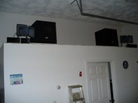
4. Receiving end; laser beam lights up toslink rx at left; middle stack from bottom: 'sharc stak', Ultramatch, 6x power amp for horns, 2x power amp for woofers and 'backup' 5.8G video receiver on top.
5. A shot of speaker array, to right of amps atop boiler room.
Recently I was faced with the issue of how to modernize my sources. I had used my fairly large garage to build a stereo 4-way array of loudspeakers, reduce my signal-processing (EQ, Xover) needs to a homebuilt box housing two Minisharcs running FIR filters built from member POS' RePhase, one as a fullband EQ, the second in the 'sharc stack' as 2x4 xover. Power amps proved surprisingly easy, inexpensive class D (or AB) chip-amp boards easily being able to drive the 15" woofers and horn-loaded higher-register drivers to monstrous levels without visible (simple scope I/O comparison) or audible distortion while sounding crystal clear at all volumes. After much work, I was clearly being hampered by my heretofore-neglected sources --- an FM tuner with rabbit ears and a small CD/DVD player.
Clearly, my desktop computer was a prime candidate, but it is housed in a small office some 45 feet away. Stringing a 60' or more cable in the open was out of the question, as was routing one through the walls. Wireless seemed to be the solution, but how?
The first solution (still in operation as a backup) was the following:
1. purchase an inexpensive USB-to-SPDIF converter (of course),
2. purchase an inexpensive Tx/Rx AV pair (composite video with R/L analog audio) and use the respective video in/out to send/receive SPDIF. Direct SPDIF plugin on each end. Works like a charm.
But curiosity got the better of me (it is a hobby, after all) and I wondered why a laser couldn't send digital audio to a toslink receiver as easily as a cable. The answer again was simpler than expected after a week or three of struggling with ideas and waiting for very cheap parts (many of which alas will have to await another project, but so what). The resulting setup, working right now sending a stream of the BSO to my sharcs, was made this way:
1. purchase an SPDIF-to-toslink converter (about $12) and its counterpart toslink-to-SPDIF converter (again ~$12),
2. remove the former from its case. It contains an RCA socket, a 75 ohm termination, a transistor and a 7404-family inverter and several resistors and caps. These remain intact.
3. It also contains an integrated 3-pin optical output unit, fed the output of the inverters, a ground line and a power line. This is the only thing removed (it may be glued --- try iso alcohol).
4. now the interesting part: order a small, cheap (mine were 10/$8) laser module, 5mW, 650nm. Mine are 6mm copper/gold colored with red/white pigtails. Construct a support circuit. Mine consists of a 100 kohm input-impedance shunt, a 68uF cap (for DC isolation between the boards, probably not necessary), and a resistor pair for output gain from the single-supply amp. I chose the ADA4891-1 with video GBWP. I also splurged for a small spring-loaded SOIC-to-DIP pin converter so I could handle the absurdly small op amp. It has 125mA output, easily enough to drive the small laser.
Since I had no idea what I was doing (the laser was a mystery... what were the thresholds, did it have a killer slow-turn-on protective mechanism, etc.) I used a 25k board-size pot I had on hand to act as both of my resistors (wiper to -in, one leg to output, the other to ground) and simply 'tuned' it to the best output. In my prototype's case I was using an older converter unit. It looked the same as the one used in the boxed current model superficially and generated a nice rail-to-rail (0 to ~4.3v) square wave for output to the laser. The 'beta test' boxed module's toslink converter looks identical as mentioned but it fed an inadequate 1v power to its (presumably) higher-bandwidth output module and seemed to have output grounding separate from input, unlike the other. It turned out that this was due to board damage incurred while removing the toslink diode module. It remains in use anyway as signal transmission results are indistinguishable. I sent 'real' ground and 4.2v supply voltage to my laser board. This 'beta test' model (sending the BSO as I type) outputs a 2v p-p signal with 2v DC offset to the laser.
The laser handles either input signal. Apparently it lacks any slow-turn-on protection since it modulates effectively with either 0-4v or 2-4v p-p digital signaling. About 40' away, the face of the toslink receiver is lit bright red. Hint: I found at test distance (about 1') that things worked best if the laser was not focused directly at the receiver's photodiode. Saturation? Don't know. But a strip of plain old translucent Scotch 'magic' tape stretched across the square toslink opening on the receiver solved everything, diffusing the light and also serving to widen the hot spot. It's a great beam-error corrector.
The setup is impervious to ambient light (tested today with all 32 long-tube flourescents turned on, plus a lot of sunlight, even bright LED flashlights). There is no need to modulate/demodulate the signal as on my 5.8G wireless. There is no seeming possibility of interference (unless I block the laser path with my hand). It can't interfere with my wifi. My setups have an aggregate 30 hours or so on them now, including continuous spans over 6 hours. The tiny laser's beam spreads to about 1" at distance, still plenty bright enough to excite the photodiode through the tape with minimal fussiness over beam placement. The laser sits next to the box housing the 2 boards, mounted in the alligator clip of a 'third hand' board soldering holder/magnifier. It makes laser alignment simple. It also acts as a good heat sink. It costs $5-$10. The box has an oversize banana-pin connector for the laser wires (silly but use what you've got on hand if possible, I always say). Be aware that the laser case is usually 'hot', i.e. mine shows 2.2v DC-average, about half the rail span.
The laser-sent signal (or the 5.8G AV 'backup plan' signal) are fed to a pre-sharc Ultramatch, which acts not only as a mixer of sorts but also as an indicator of signal integrity with its array of informative LEDs on the front panel. It's not absolutely necessary but it's very helpful.
Caveat: I generally send 48k/24bit SPDIF from the computer. Since the Minisharcs run a 48k plugin there's no point to using higher rates. Depending on the laser amp you choose, I believe a good deal higher is practical. The 5.8G wireless AV will send 48/24 tops. The laser is confirmed to 96/24 (as high as the Ultramatch goes).
Clearly a better job can be done with more analysis, but at this point I am waiting for operational bugs to show up so I can fix them rather than obsess about perfection (I do that enough). Some photos are attached.
Notes on attached photos:
1. The 'box' on left, laser mounted on board-holder on right.
2. Shot across garage to receiver to illustrate the distance.
3. Laser at a distance (small thing over door; to-be-improved power wire and spdif cable at left).
4. Receiving end; laser beam lights up toslink rx at left; middle stack from bottom: 'sharc stak', Ultramatch, 6x power amp for horns, 2x power amp for woofers and 'backup' 5.8G video receiver on top.
5. A shot of speaker array, to right of amps atop boiler room.
Attachments

Last edited:
Addendum: Finally got a chance to check the twin of the spdif-to-toslink converter currently in use. The 'separate ground' and 1v power out mentioned in the text on the now-bare toslink diode pad were the result of my damaging the board when removing the diode module. Ground is ground, output (as with my older prototype unit) is 4.5v. So AFAIK they're all the same. Test them anyway. I've edited the post.
laser driver
Here is a laser driver schematic based on what I'm using with my particular modified converter. Note that the 3 inputs all come from the converter board, and should be available from the 3 holes left behind after removing the optical sending module.
Here is a laser driver schematic based on what I'm using with my particular modified converter. Note that the 3 inputs all come from the converter board, and should be available from the 3 holes left behind after removing the optical sending module.
Attachments
Just an update... system as described verified to 192/24. Had to bypass the Ultramatch (96k max) and go straight to the Digi-FP (216k input max) in front of the minisharcs to confirm, but it works.
Radical simplification
I suppose it's a good thing when you progress past stage 1 and find that things have gotten simpler. It's usually what happens to me as I tend to overcomplicate out of caution.
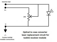
Stage 2 is playing now at 192/24 directly into the Digi-FP (the only port to the amps that has 192 read capacity). As I continue to await delivery of a few AD8000 very-high-bw op amps, I find that the laser driver stage spec'd above, while it works fine, may not be necessary at all. With the simple addition of a trim pot to act as a pullup for the inverter output of the ~$15 coax/optical converter, along with replacement of the supplied wallwart power supply with a nice $20 5V/1A regulated switching supply, I find that the simple mod shown permits the inverter to directly drive the laser with a 0.8v p-p spdif signal riding atop 3.3v DC offset. Though things work with a full 4.5v p-p signal and no offset, the offset method permits the laser to reach full brightness for range. The only drawback is that I can't use my ultramatch (96k max) and I miss the light show, but I'll get over it.
Both of the little converters used (coax/opt to drive the laser, opt/coax to receive) run 74HC04 inverters and are spec'd to 192. Guess they weren't kidding. Doesn't get much easier than this:
I suppose it's a good thing when you progress past stage 1 and find that things have gotten simpler. It's usually what happens to me as I tend to overcomplicate out of caution.
Stage 2 is playing now at 192/24 directly into the Digi-FP (the only port to the amps that has 192 read capacity). As I continue to await delivery of a few AD8000 very-high-bw op amps, I find that the laser driver stage spec'd above, while it works fine, may not be necessary at all. With the simple addition of a trim pot to act as a pullup for the inverter output of the ~$15 coax/optical converter, along with replacement of the supplied wallwart power supply with a nice $20 5V/1A regulated switching supply, I find that the simple mod shown permits the inverter to directly drive the laser with a 0.8v p-p spdif signal riding atop 3.3v DC offset. Though things work with a full 4.5v p-p signal and no offset, the offset method permits the laser to reach full brightness for range. The only drawback is that I can't use my ultramatch (96k max) and I miss the light show, but I'll get over it.
Both of the little converters used (coax/opt to drive the laser, opt/coax to receive) run 74HC04 inverters and are spec'd to 192. Guess they weren't kidding. Doesn't get much easier than this:
Attachments
Radical simplification #2
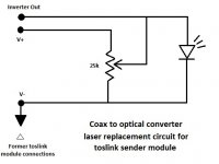
Just to add to this theme, I find that even the optical/spdif converter on the destination end can be eliminated as long as your destination processor has an optical input. A simple toslink cable illuminated by the laser produces excellent results, and with an active stage removed! Tested so far at 96k (because the most convenient optical destination port is on the ultramatch; I'm quite sure 192 will work fine with Digi-FP's optical connection port). Hint: anchor your destination, whether it's the optical/coax converter or just the toslink cable, to a small 4"x4" 'lab jack'. Then should the laser's aim drift a bit over time (which it does, the 40' distance in my case being a factor) you can simply adjust the lab jack a bit rather than try to reaim the laser. Velcro works fine as anchoring material. So does plain scotch tape.
I know this is starting to sound ridiculous, let alone for HD audio transmission, but try it. You can afford it. I'm finding I'm not the only one who overcomplicates things, it seems.
Error fix for "radical simplification" diagram
Sorry, in my haste I labeled the converter 'optical to coax' and the removed toslink module as 'receiver'. Of course it should be 'coax to optical' converter and 'sender' toslink module. Corrected diagram labeling here. Apologize for any confusion.
Sorry, in my haste I labeled the converter 'optical to coax' and the removed toslink module as 'receiver'. Of course it should be 'coax to optical' converter and 'sender' toslink module. Corrected diagram labeling here. Apologize for any confusion.
Attachments
Cool stuff and that wasn't at all what I was expecting from the thread title, but nice nontheless.
If you think SOIC parts are absurdly small you should try some of the really small parts. 🙂
If you think SOIC parts are absurdly small you should try some of the really small parts. 🙂
It's a neat concept, one that I was interested in this in the past. Here is an interesting web page on the subject, called: A S/PDIF Free Space Digital Audio Optical Link
It's only practical for line-of-sight communication, unless you want to use a bunch of mirrors (like the web page at the link). Now I just use my WiFi network and stream PCM (or FLAC) and I can cover my whole house. Less chance for retina damage, too! 🙂
It's only practical for line-of-sight communication, unless you want to use a bunch of mirrors (like the web page at the link). Now I just use my WiFi network and stream PCM (or FLAC) and I can cover my whole house. Less chance for retina damage, too! 🙂
Last edited:
Cool stuff and that wasn't at all what I was expecting from the thread title, but nice nontheless.
If you think SOIC parts are absurdly small you should try some of the really small parts. 🙂
Yeah, my bad on the title no doubt. I have encountered some of those really small parts on my amp boards. They are doom and gloom for DIY.
I saw that web page, and in fact found later a youtube video of a guy demonstrating spdif over a modified toslink converter. No details were given, and it seemed from the laser brightness that range would have been an issue. I think he did not bias up his signal to crank the diode into full output.It's a neat concept, one that I was interested in this in the past. Here is an interesting web page on the subject, called: A S/PDIF Free Space Digital Audio Optical Link
It's only practical for line-of-sight communication, unless you want to use a bunch of mirrors (like the web page at the link). Now I just use my WiFi network and stream PCM (or FLAC) and I can cover my whole house. Less chance for retina damage, too! 🙂
No doubt on line of sight, but that was optimal for my case. I decided I had enough pummeling from microwaves already 🙂 I plan to try mirrors, but right now I'm still too stunned that I'm listening to 192/24 piped through about $40 worth of equipment!
Update
Since my last post, I've modified the laser driver/receiver with good results. Here are some details for those interested in giving this a try.
First, the coax/toslink converter I modified has the name TOF-820. It is a marvelously simple and cheap little beast, essentially a balun that converts. It contains a 74hc04 inverter as its active component (besides the toslink diode module, which is removed as mentioned before. It (and its sister TOF-830, used as a receiver) are widely available.
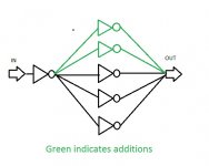
The inverter takes the DC-stripped and rebiased coax signal input and feeds it to one inverter. This fans out to 3 more inverters, which are fanned back into a single output that is mildly conditioned with a few caps/resistors before reaching the laser. I found that adding the remaining 2 unused inverters to the fan out/in output array produces better squarewave output, perhaps due to increased current capability. I made this same fanout mod to the TOF-830 toslink-to-coax module that serves as my receiver for the laser's signal, btw.
How good is it? My cm6631a-driven usb-to-spdif converter accepts 192/32 output from my computer (and foobar2000) and (I assume with some test justification) converts it to 192/24. Works perfectly. However, I'm given the driver option of 384/32. This results in no sound. Why, I wondered. So my scope checked the output of my receiver module. Turns out it is being sent spdif at 384k! The usb converter doesn't downsample to 192. That's good and bad. Bad because I can't find anything yet that will sample-rate downconvert a 384/24 signal. But good because I can generate one, and my scope (at its timebase limits) shows what seems to be a perfectly readable signal, simply beyond the bitrate limits of my Digi-FP front-end on my DSP.
I plan to try old-fashioned TTL 74F04 inverters next. Not cmos, but with slightly faster rise/fall times (and somewhat decreased current capacity, which I believe the fanout will cure).
By the way, the laser modules I currently use look like this:
1 Pc DC 5V 5mW 650nm 6mm Laser Dot Diode Module Red Copper Head Tube Dot-shaped - US$1.10
They are very cheap and widely available also. They have the virtue of just enough micro support circuitry to keep the laser alive and well, and just little enough so as not to interfere with its bandwidth capability.
Since my last post, I've modified the laser driver/receiver with good results. Here are some details for those interested in giving this a try.
First, the coax/toslink converter I modified has the name TOF-820. It is a marvelously simple and cheap little beast, essentially a balun that converts. It contains a 74hc04 inverter as its active component (besides the toslink diode module, which is removed as mentioned before. It (and its sister TOF-830, used as a receiver) are widely available.
The inverter takes the DC-stripped and rebiased coax signal input and feeds it to one inverter. This fans out to 3 more inverters, which are fanned back into a single output that is mildly conditioned with a few caps/resistors before reaching the laser. I found that adding the remaining 2 unused inverters to the fan out/in output array produces better squarewave output, perhaps due to increased current capability. I made this same fanout mod to the TOF-830 toslink-to-coax module that serves as my receiver for the laser's signal, btw.
How good is it? My cm6631a-driven usb-to-spdif converter accepts 192/32 output from my computer (and foobar2000) and (I assume with some test justification) converts it to 192/24. Works perfectly. However, I'm given the driver option of 384/32. This results in no sound. Why, I wondered. So my scope checked the output of my receiver module. Turns out it is being sent spdif at 384k! The usb converter doesn't downsample to 192. That's good and bad. Bad because I can't find anything yet that will sample-rate downconvert a 384/24 signal. But good because I can generate one, and my scope (at its timebase limits) shows what seems to be a perfectly readable signal, simply beyond the bitrate limits of my Digi-FP front-end on my DSP.
I plan to try old-fashioned TTL 74F04 inverters next. Not cmos, but with slightly faster rise/fall times (and somewhat decreased current capacity, which I believe the fanout will cure).
By the way, the laser modules I currently use look like this:
1 Pc DC 5V 5mW 650nm 6mm Laser Dot Diode Module Red Copper Head Tube Dot-shaped - US$1.10
They are very cheap and widely available also. They have the virtue of just enough micro support circuitry to keep the laser alive and well, and just little enough so as not to interfere with its bandwidth capability.
Inverter update
Just a check-in on progress.
I made a test pof820 by performing mods as specified before and replacing the 74hc04 with a socket. Still works perfectly with 74hc04; 74f04 is a no-go. Stick with cmos.
The setup, btw, has been running problem-free for a couple of months now (in one incarnation or another). I could not get a 12mm laser module with focusable lens to work (too much support circuitry; will try some more) but I machined one of the cases out to install one of the 6mm lasers (with epoxy) and mount the result in a standard laser mount. Continues to work perfectly at all sample rates available.
Here is an attachment of how the inverter fanout was modified, as previously mentioned.
Attachments
Update on this project: I had expected by now to report either some improvement mods or to have a lifespan on the laser module, but the exact same unit as described is still in daily multi-hour operation at 192k sample rate with no sign of impending failure after nearly a year. I have forgotten several times to power down the laser unit overnight, so it has some unintended 15-hour tests also, running an idle pattern. One receiving-end change is that the receiving DSPs have been replaced by a desktop with 7.1 soundcard and DSP apps, the soundcard having optical input. Thus the receiving unit has been replaced by the open end of an optical cable connected to the soundcard input.
I haven't modified anything in the sending unit since nothing seems necessary.
I haven't modified anything in the sending unit since nothing seems necessary.
Well, at 650nm the only hazard would be staring directly into it, and even that can't burn your eye since there's no IR component (though the discomfort would deter you anyway). I have laser pointers, laser levels, laser rangefinders and laser-guided IR thermometers which can more easily be pointed at someone. The laser is stationary and mounted high so I can move around without disrupting the path (or looking directly at it).
Visible light can burn too. Don't run away with the false idea that only IR has a heating effect. IR is especially dangerous because as well as heating just like visible, you cannot see it. Most of the other things you mention are likely to be more like 0.5mW power and so much safer.
5mW monochromatic red can of course cause temporary flash blindness, and prolonged exposure is certain to cause photochemical damage ("burns") to your retina, but you will have a difficult time trying to burn a hole through anything with it.
A 5mW visible laser is defined as class IIIa, described as "Lasers similar to Class 2 with the exception that collecting optics cannot be used to directly view the beam." Class II is "Visible lasers considered incapable of emitting laser radiation at levels that are known to cause skin or eye injury within the time period of the human eye aversion response (0.25 seconds)." Wikipedia offers this description: "Lasers in this class are mostly dangerous in combination with optical instruments which change the beam diameter or power density, though even without optical instrument enhancement direct contact with the eye for over two minutes may cause serious damage to the retina. Output power does not exceed 5 mW."
A new set of standards (not used in the US by the FDA) classifies the laser as 3R: "A Class 3R laser is considered safe if handled carefully, with restricted beam viewing. With a class 3R laser, the MPE can be exceeded, but with a low risk of injury. Visible continuous lasers in Class 3R are limited to 5 mW", again via Wikipedia.
Both standards say basically the same thing, i.e. don't stare into it. Good advice. BTW, the laser I've mentioned is unfocusable and has a great deal of spot diffusion. For my purposes that's good, since it provides a wide spot to compensate for any slight beam drift due to ambient temperature variation et al. Certainly a lower-power laser could be used; the one I chose was simply the first I tried that worked (i.e., had fast enough rise time undamped by support circuitry). The choice of 650nm was mandated by the fact that it replaces a Toslink sender/cable.
OK. You have obviously investigated the safety issues. I was just concerned that someone might copy your idea without thinking.
- Status
- Not open for further replies.
- Home
- Source & Line
- Digital Source
- Thoroughly Affordable Wireless Toslink.