Of course it depends on designers. Some actually can do it. This video shows the first short term full power test performed on a prototype using 2x IRS20957 and 4x TO-220 IRFB4615, bridged into 5.6r resistor bank load, with single-stage PFC SMPS. Duration is short because heatsinking and long term protections are not yet fully functional. PSU uses approx. the volume of a "SMPS400" (12x8x5cm). The 2 class-D channels occupy a similar volume too.
https://youtu.be/ztISHByR88s
Left red led display shows input power in W, 90% efficiency, ~1600W output. Right red led display shows line voltage (a low quality line simulated with variac and transformers, V on the low side and with substantial drop) to demonstrate capabilities of PSU. Oscilloscope shows voltage waveform at collectors of PSU IGBTs (100V/div) synchronized with mains half-cycle peak.
Last edited:
Eva could you attach some of the missing pics from your posts way back? Mostly about snubbers and oscillation.
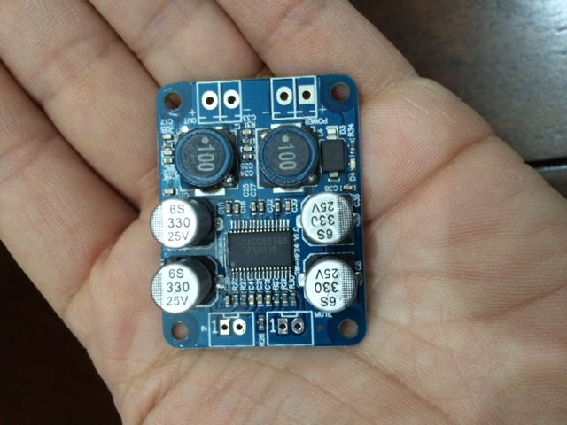
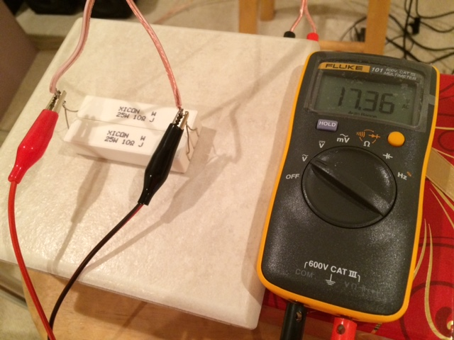
I ran a stress test on the tiny Sanwu 3118 PBTL amp and got an honest 60w (rated) into a dummy 5ohm load. It was quite impressive to see a postage stamp sized amp cook a pair of power resistors.
http://www.diyaudio.com/forums/clas...ing-them-everything-comes-25.html#post4585203
http://www.diyaudio.com/forums/clas...ing-them-everything-comes-25.html#post4585203
Hi Eva,
let's see how much you are willing to tell the world.
Are you going to tell us that this is a flyback? With 1.6...1.8kW?
May be a half bridge flyback?
It looks like at lower power it would run in discontinuous mode - but why without valley switching?
And then towards higher power it is changing over to continuous mode, looks like fixed frequency during continuous mode.
If you do not let us starve in our clueless mental misery, then this could become a 😎😎 thread !
Your preferred control method to handle the transition between discontinuous and continuous mode?
Schematics?
Transformer size and construction...?
Not considering dual phase with interleaved operation?
...?
Anything else you want to show to us?
P.S.
Please do not get angry with me when you start showing key informations,
while I will stick to asking and drawing information. Sorry for this, SMPS simply has too much of overlap with my work and I don't want to come even close to the point of potential IP conflicts.
Of course it depends on designers. Some actually can do it. This video shows the first short term full power test performed on a prototype using 2x IRS20957 and 4x TO-220 IRFB4615, bridged into 5.6r resistor bank load, with single-stage PFC SMPS. Duration is short because heatsinking and long term protections are not yet fully functional. PSU uses approx. the volume of a "SMPS400" (12x8x5cm). The 2 class-D channels occupy a similar volume too.
https://youtu.be/ztISHByR88s
Left red led display shows input power in W, 90% efficiency, ~1600W output. Right red led display shows line voltage (a low quality line simulated with variac and transformers, V on the low side and with substantial drop) to demonstrate capabilities of PSU. Oscilloscope shows voltage waveform at collectors of PSU IGBTs (100V/div) synchronized with mains half-cycle peak.
Where is the pictures?
What is the rail voltage?
What's the advantage\difference between the 20957 and 2092?
Thanks for the great input!!
What's the advantage\difference between the 20957 and 2092?
Thanks for the great input!!
IRS2092 is a complete class d amplifier wich has built in a OTA (transconductance operational amplifier) ,comparator,and driver(IRS20957) but it has prefilter feedback,and the IRS20957 is a great little driver with PWM input,dead time control and adjustment from 15 to 45ns and overcurrent protection
advantage for IRS2092 is that it's straight forward for beginers
advantage for IRS20957 is that lets you use any (modulator) modulation scheme you want 🙂
ps. also IRS2092 has dead time and OCP 🙂
advantage for IRS2092 is that it's straight forward for beginers
advantage for IRS20957 is that lets you use any (modulator) modulation scheme you want 🙂
ps. also IRS2092 has dead time and OCP 🙂
Hi Eva,
let's see how much you are willing to tell the world.
Are you going to tell us that this is a flyback? With 1.6...1.8kW?
May be a half bridge flyback?
It looks like at lower power it would run in discontinuous mode - but why without valley switching?
And then towards higher power it is changing over to continuous mode, looks like fixed frequency during continuous mode.
If you do not let us starve in our clueless mental misery, then this could become a 😎😎 thread !
Your preferred control method to handle the transition between discontinuous and continuous mode?
Schematics?
Transformer size and construction...?
Not considering dual phase with interleaved operation?
...?
Anything else you want to show to us?
P.S.
Please do not get angry with me when you start showing key informations,
while I will stick to asking and drawing information. Sorry for this, SMPS simply has too much of overlap with my work and I don't want to come even close to the point of potential IP conflicts.
Choco:
It's a resonant flyback that uses a high side switch to a capacitor. There is valley-switch, but in trade for circuit simplicity it becomes inaccurate at very low power, when Fsw is < 30khz. There is ZCS too, achieved with a capacitor in parallel with primary. There is also an auxiliary switch with coil and reset diodes to achieve ZVS of low side. High side is inherently ZVS. Main switches are IGBTs with diode, similar to the ones used for induction cooking.
Control method is self-oscillating, based in charge integration (like self-osc class D), it does PFC apart from optimally sequencing and timing the complex power stage and handling reactive elements, it uses comparators and timers, half analog half digital, MCU based. It's a 4-stroke converter, where there are one or more conditions that end one stroke and start the next. Additionally, a low limit is put on Fsw and below that it does on/off modulation or pulse skip (this part is in process of optimization).
The voltage loop is digital, with line frequency measurement, a special continuously-self-tuned IIR comb filter, line R measurement and feed-forward, fast comb-based line V^2 feed-forward, and other gadgets to achieve full step response in one mains cycle. A complex voltage loop involving learning algorithms that results in cleanest line current and output voltage responses possible at high proportional gain, without use of integrator. I'm already starting to tell too much, so only one more thing, transformer is E42/20 with big gap and full of litz (actually I made the transformer protos with materials from old projects haha).
Last edited:
Ti has offerings using F2803x (Piccolo family) that allows Digital and Analogue Domain power control, its far more superior in many ways compared to the stuff you talking about.(Your designs are using outdated PIC32 MCU`s)
They also have a plug-in built into the IDE to manage coefficient calculations for the signal controller.
You haven`t made an impression, on me that is, its been a while since you been on this forum and things from the perspective of MCU/signal progressing and FPGA innovation has made 10 fold leaps ahead compared to your work dating as far back as +10 years ago. Learning algorithms you say?... nothing new, anyone doing Computer Science this day and age, partnered with someone with an EE background can do Regression Algorithms even on a MCU with enough memory. (which is the norm today)
Spare us the pompous feedback and show something useful.
Last edited:
Why so hateful mate?
😀 that wasn`t hate, just my response to a pompous view. really dont have hate, she contributed much more than most here including me, but that pompous ways.

"Spare us the pompous feedback" - oh come on.Ti has offerings using F2803x (Piccolo family) that allows Digital and Analogue Domain power control, its far more superior in many ways compared to the stuff you talking about.(Your designs are using outdated PIC32 MCU`s)
They also have a plug-in built into the IDE to manage coefficient calculations for the signal controller.
You haven`t made an impression, on me that is, its been a while since you been on this forum and things from the perspective of MCU/signal progressing and FPGA innovation has made 10 fold leaps ahead compared to your work dating as far back as +10 years ago. Learning algorithms you say?... nothing new, anyone doing Computer Science this day and age, partnered with someone with an EE background can do Regression Algorithms even on a MCU with enough memory. (which is the norm today)
Spare us the pompous feedback and show something useful.
Why should Eva drop >$2K on Code Composer Studio and an emulator for the C2000 chip, and spend potentially months developing software for it and potentially having to do multiple hardware iterations, when what she's built does the job just fine?
And FPGAs/DSPs in switching power supplies is hardly the norm these days - haul apart pretty much any consumer SMPS and you'll be lucky if you even find an 8 bit micro. In high end industrial equipment like high power inverters, -48V telecom rectifiers, etc... where a couple percent efficiency improvement means everything, and you're selling potentially hundreds of thousands of units which pays for the large engineering team working on the thing, sure, you might find a DSP.
You really expect someone operating out of their house, building a one-off power supply/amplifier, to go through all that effort? C'mon.
"Spare us the pompous feedback" - oh come on.
Why should Eva drop >$2K on Code Composer Studio and an emulator for the C2000 chip, and spend potentially months developing software for it and potentially having to do multiple hardware iterations, when what she's built does the job just fine?
CCS can be used for free forever (no time limit, no performance limit, no code size limit) with a XDS100 JTAG debugger
"Spare us the pompous feedback" - oh come on.
And FPGAs/DSPs in switching power supplies is hardly the norm these days - haul apart pretty much any consumer SMPS and you'll be lucky if you even find an 8 bit micro. In high end industrial equipment like high power inverters, -48V telecom rectifiers, etc... where a couple percent efficiency improvement means everything, and you're selling potentially hundreds of thousands of units which pays for the large engineering team working on the thing, sure, you might find a DSP.
You really expect someone operating out of their house, building a one-off power supply/amplifier, to go through all that effort? C'mon.
Yes, its actually becoming very normal these days and microcontrollers are becoming highly specialized, eclipsing the role of a DSP and offering supervisory capabilities with an arsenal of peripherals. Its even more attractive to keep things in the firmware for smaller R&D garage companies as the IP sits in firmware, with a smaller yield.
Last edited:
The XDS100 doesn't do trace or profiling, which is something you really want for a realtime application like a SMPS which can go bang (and make the load go bang too) if a bug happens. You'll want a XDS200 or XDS560 for "real" work, which means buying the full CCS package.CCS can be used for free forever (no time limit, no performance limit, no code size limit) with a XDS100 JTAG debugger
Though correction on the tools, the full C2000 tools price is now $495 USD, a lot cheaper than last time we purchased them here at work.
My point still stands that Eva's design is built and working and does the job it was intended to.Yes, its actually becoming very normal these days and microcontrollers are becoming highly specialized, eclipsing the role of a DSP and offering supervisory capabilities with an arsenal of peripherals. Its even more attractive to keep things in the firmware for smaller R&D garage companies as the IP sits in firmware, with a smaller yield.
Sure, it's not technologically advanced to satisfy some random person on the internet, but does that matter?
😀 My intention is not to hijack this thread so please forgive me.
With the turn over generated from a small serious project $495 is really nothing, I do get your point, however anyone serious in this area wont mine that sort of cost. Heck some people will go to the extent and just use a licence key from a friend 😉 just to get the job done and later with due diligence buy the software tools. That`s how the real world works when operating from a garage.
With the turn over generated from a small serious project $495 is really nothing, I do get your point, however anyone serious in this area wont mine that sort of cost. Heck some people will go to the extent and just use a licence key from a friend 😉 just to get the job done and later with due diligence buy the software tools. That`s how the real world works when operating from a garage.
The approach that TI and others promote to control SMPS through brute force (high speed ADC, all calculations in digital domain, high speed PWM) results from lack of communication and understanding between analog and digital designers, which in practice turns into unnoticed redundancy.
They are trying to generalize control methods and create products for something that cannot be generalized optimally. As a result, after many years of development of products for powerful digital control of analog loops, these still find little or no use for real-world power conversion, people still using old analog control ICs and schemes.
Brute force ADC/math/PWM is neither the best method nor the most accurate for controlling the inner current loops of SMPS, it is just the easiest method to describe and sell, it requires huge amounts of digital processing power (and power supply power) because all calculations are moved to the core of the MCU.
Many of these calculations are better done with comparators, DACs and clever use of mixed analog-digital elements, because ADC and PWM signal conditioning alone have a similar complexity and cost while still leaving the calculations unsolved.
For example turning a current transformer into a resettable current integrator by loading it with a FET and a capacitor. Then this is wired to a comparator built into the MCU that is configured to act on the PWM module. The other input to the comparator comes from a voltage integrator. Voila! Accurate self-oscillating PFC current loop, without significant use of CPU power. How much MIPS of DSP-ing does this save? In TI chips they just forgot about comparators, there are some disciplines they do not master haha (edit: Looking at F2803x data I notice that there are 3 DACs attached to the 3 comparators, but these DACs do not have a variable Vref, forcing A/D and D/A for any analog gain control. Hilarious. DACs with analog references can be used as real time analog*digital multipliers, saving A/D and D/A.)
Additionally I do not use compilers at all. I was already into assembler programming 20 years ago, before starting with power electronics. I develop mixed analog-digital algorithms optimized to use the least amount of elements. I write these generic algorithms in pseudo-code similar to C that can be translated to any other language. Then I do the compilation manually. All subsequent editing coming from testing is performed both over compiled and non-compiled code. As a result I routinely get 2x-3x more processing power from MCUs than someone else paying for a compiler. It just took me one year to learn MIPS, which is a well documented coding standard. Most of the CPU cores TI use have non-standard and usually non-documented instruction sets (buy our compiler, do it like us, or don't use our products, no room for creativity as a result).
This 8 bit MCU has 4 comparators, 4 SMPS control modules and 3 op-amps built-in. Enough to get 2KW from a E42/20 transformer: PIC16F1789 - 8-bit PIC Microcontrollers
The 32 bit MCU which is like 10 times more powerful is being used to deal in real time with 4 amplifier channels (from pulse by pulse supervision to voice coil temperature monitoring without extra wires) and other stuff. Again, I tried but no way to do this with TI chips, not enough ADC channels.
Microchip, while making less powerful stuff (as seen on paper), and sometimes over-valuating the stuff they make, have a sense to dimension and lay out things in ways more suitable for real-world optimized applications.
Last edited:
The approach that TI and others promote to control SMPS through brute force (high speed ADC, all calculations in digital domain, high speed PWM) results from lack of communication and understanding between analog and digital designers, which in practice turns into unnoticed redundancy.
They are trying to generalize control methods and create products for something that cannot be generalized optimally. As a result, after many years of development of products for powerful digital control of analog loops, these still find little or no use for real-world power conversion, people still using old analog control ICs and schemes.
Brute force ADC/math/PWM is neither the best method nor the most accurate for controlling the inner current loops of SMPS, it is just the easiest method to describe and sell, it requires huge amounts of digital processing power (and power supply power) because all calculations are moved to the core of the MCU.
True (but only to some extent), actually, commercial companies are using Ti products in high reliable power conversion products example, Sunnyboy SMA (European Company) develops inverter technology that uses a TMS320 (DSP). I do advocate a hybrid design both Analog/Digital.
Here is an example of the SMA inverter unit with the main Ti DSP
mounted on the board https://www.youtube.com/watch?v=RtcYnZj5Aew
This is not true. PIC`s suffer from this problem, most of them does not have a hardware FPU on the die and uses libraries to perform IEE 754 floating point conversion (only the high end ones like the PIC32 I think have a FPU). On the other a humble STM32 (ARM Core) has a built in hardware FPU so there is no "brute force" work required here and the Ti part I mentioned has a FPU built in as well.Brute force ADC/math/PWM is neither the best method nor the most accurate for controlling the inner current loops of SMPS, it is just the easiest method to describe and sell, it requires huge amounts of digital processing power (and power supply power) because all calculations are moved to the core of the MCU.
Today as it stands, there is no reason (today) to waste time optimising code given the large complex code base software engineers maintain, a human cannot (given the complexity of the code) become a human optimiser that`s the job of a complier, well.. unless certain critical math routine needs attention down to CPU tick timing level optimisation, but this is usually a small memory footprint.The point is there is no point or gain at trying to beat the complier at the job it was designed to do.Then I do the compilation manually. All subsequent editing coming from testing is performed both over compiled and non-compiled code. As a result I routinely get 2x-3x more processing power from MCUs than someone else paying for a compiler. It just took me one year to learn MIPS, which is a well documented coding standard. Most of the CPU cores TI use have non-standard and usually non-documented instruction sets (buy our compiler, do it like us, or don't use our products, no room for creativity as a result).
This is Microchip`s biggest strengths, large peripheral offerings, and long shelf life. However they have an awful IDE (riddled with issues) and their tools like the PICKIT suffers from all kinds of problems like jumping break points and cannot handle medium to large projects (its just too slow) its replacement for productive work is an ICD3 which costs $250 a considerable amount more than a pickkit3.This 8 bit MCU has 4 comparators, 4 SMPS control modules and 3 op-amps built-in. Enough to get 2KW from a E42/20 transformer: PIC16F1789 - 8-bit PIC Microcontrollers
The 32 bit MCU which is like 10 times more powerful is being used to deal in real time with 4 amplifier channels (from pulse by pulse supervision to voice coil temperature monitoring without extra wires) and other stuff. Again, I tried but no way to do this with TI chips, not enough ADC channels.
Last edited:
FYI, the C2000 doesn't have a floating point unit either.This is not true. PIC`s suffer from this problem, most of them does not have a hardware FPU on the die and uses libraries to perform IEE 754 floating point conversion (only the high end ones like the PIC32 I think have a FPU). On the other a humble STM32 (ARM Core) has a built in hardware FPU so there is no "brute force" work required here and the Ti part I mentioned has a FPU built in as well.
FPU for a SMPS? This is like saying "I have no idea about the numeric nature of the calculations needed in a SMPS". You need more background into maths, physics and control science, not a FPU.
Actually I wrote a set of mini-floating point routines for PIC16, in order to use 8 bit exponent and 8 bit mantissa, for best speed/accuracy ratio in multiplication, squaring, square root, and division. I used to disassemble computer games in the old times, including 8-bit 3D games, fascinated about how these calculations were possible in modest CPUs.
This mini-float is specially suited for outer SMPS loops, for magnitudes sampled at 1~2khz. Only a few dozen thousand calculations of that type are really needed per second in an off-line SMPS, and these are the kind of non-linear calculations better done in digital. A 8.8 * 8.8 mini-FMUL or mini-FDIV can take <50T (if full range check is not needed). Conversions between 8~24 bit integer and 8.8 mini-float can take 10~20T. A 8-bit 8-MIPS core can handle this satisfactorily.
Last edited:
- Status
- Not open for further replies.
- Home
- Amplifiers
- Class D
- Some people wonders: Can class D do the power advertised?