So i have a bunch of KSN1005 clones that i wanted to mess around with.. but like many people have found out, they sound terrible unfiltered. I tried lots of solutions to control the frequency response in any way possible:
The crossover in this barely does anything.. extreme values only attenuate the tweeter overall:
Pulsar Developments Ltd - Piezo Tweeter Application Note
Same with this:
http://linear1.org/i/piezo.pdf
And this.. note that putting an 8 ohm resistor in parallel with the tweeter does not make it act like an 8 ohm speaker!
Using piezo tweeters wisely: a "how to" | Audiokarma Home Audio Stereo Discussion Forums
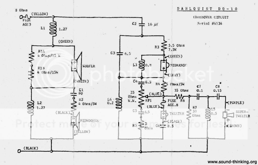
Because piezo tweeters are basically a lossy capacitor, they needed to be treated differently. The only thing i have found on the internet that seems to be right is the Dahlquist DQ-10 crossover
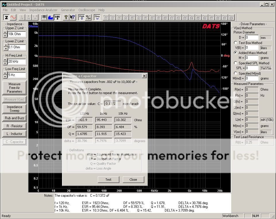
So i measured the tweeter's impedance and capacitance with the Dayton audio DATS
Then i used LTSpice to model the crossover.. there is a danger that certain L C and R combinations can cause huge resonant peaks so this is a good precaution
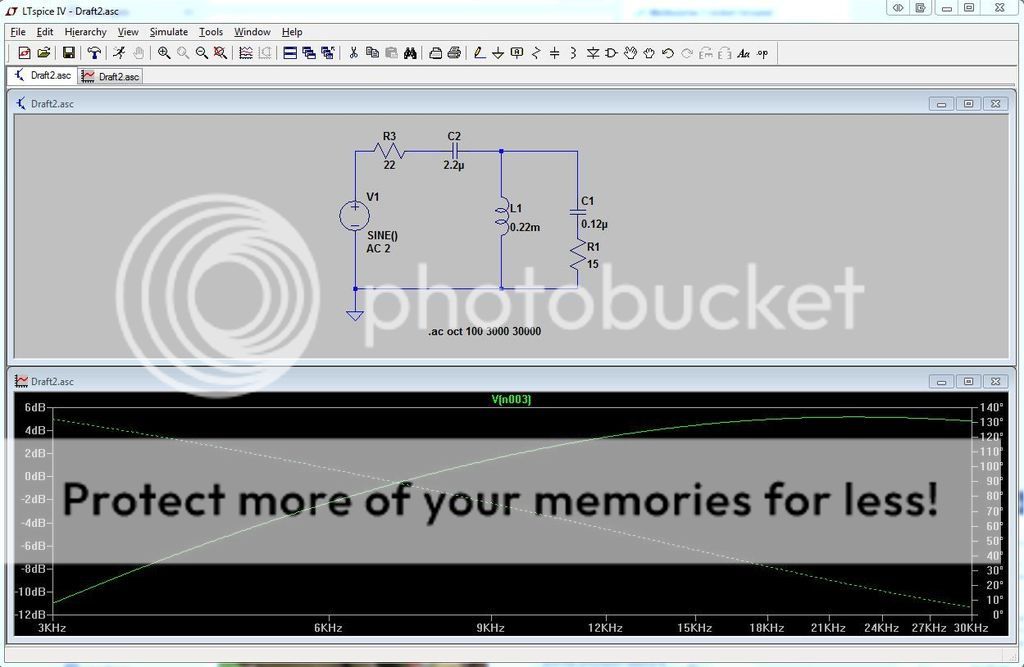
C1 and R1 are the piezo, the rest are crossover components.
The good thing about simulating this is that you can quickly change component values or even simulate a range of values and get a response graph.
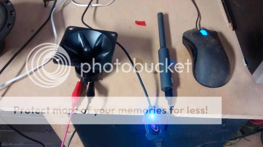
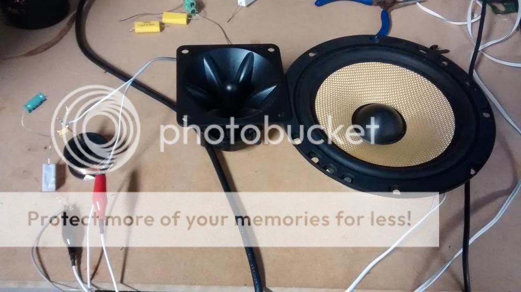
Test setup:
This is the measured frequency response stock, with the crossover, and then with a woofer (without xo) added - using a UMIK-1
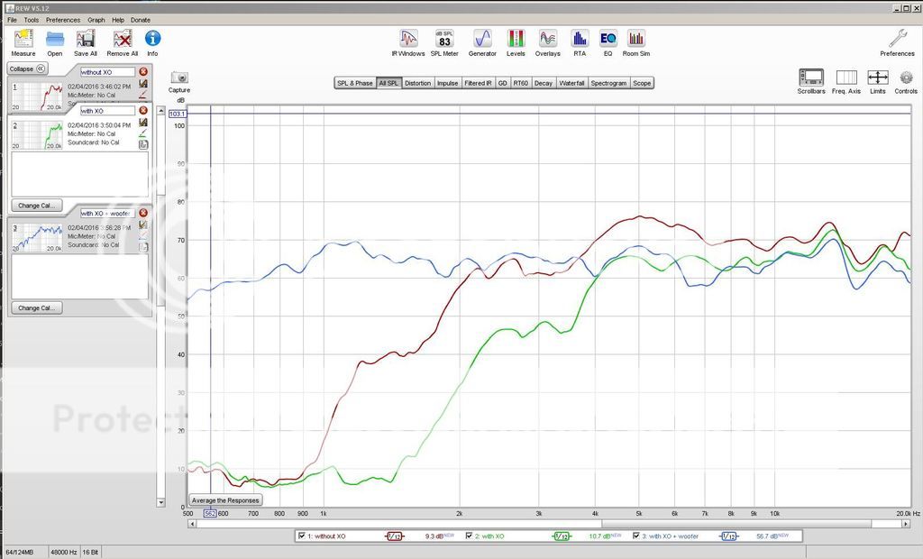
There is a very noticable sound improvement, the chirpy sound is gone and it sounds fairly delicate and detailed.
The crossover in this barely does anything.. extreme values only attenuate the tweeter overall:
Pulsar Developments Ltd - Piezo Tweeter Application Note
Same with this:
http://linear1.org/i/piezo.pdf
And this.. note that putting an 8 ohm resistor in parallel with the tweeter does not make it act like an 8 ohm speaker!
Using piezo tweeters wisely: a "how to" | Audiokarma Home Audio Stereo Discussion Forums
Because piezo tweeters are basically a lossy capacitor, they needed to be treated differently. The only thing i have found on the internet that seems to be right is the Dahlquist DQ-10 crossover
So i measured the tweeter's impedance and capacitance with the Dayton audio DATS
Then i used LTSpice to model the crossover.. there is a danger that certain L C and R combinations can cause huge resonant peaks so this is a good precaution
C1 and R1 are the piezo, the rest are crossover components.
The good thing about simulating this is that you can quickly change component values or even simulate a range of values and get a response graph.
Test setup:
This is the measured frequency response stock, with the crossover, and then with a woofer (without xo) added - using a UMIK-1
There is a very noticable sound improvement, the chirpy sound is gone and it sounds fairly delicate and detailed.
Last edited:
Nice, but you wonder if it is worth the trouble......
They are an inexpensive tweeter - are the results really good? I also have a heap of these things and I am keen to try.
They are an inexpensive tweeter - are the results really good? I also have a heap of these things and I am keen to try.
If you have the parts lying around you might as well.. you can use the values i used for a quick and easy ~4k crossover.
Once you have an LTSpice template you can also mess around with different values fairly easily:
TinyUpload.com - best file hosting solution, with no limits, totaly free
Once you have an LTSpice template you can also mess around with different values fairly easily:
TinyUpload.com - best file hosting solution, with no limits, totaly free
Looks promising. Could you change the vertical axis to something with a smaller range (like 40..80dB) to make it easier to see to which extent the response is flat? I'm also curious to see the measurements with less smoothing.
Here is a link to a thread on this topic that I think you will find very useful...
Using piezo tweeters wisely: a "how to" | Audiokarma Home Audio Stereo Discussion Forums
Using piezo tweeters wisely: a "how to" | Audiokarma Home Audio Stereo Discussion Forums
Well, you don't really need a transformer for it.
Let's make it short:
A piezo acts like a capacitor which basically means, the impedance is very high and it drops with increasing frequency. That way usual passive filters won't work. Easy solution: A parallel resistor. With the resistor the filters 'see' a (pretty much) fixed resistance and you can simply apply anything you want.
What you want to do is treat it the same way you would any other driver with a non-flat impedance. Usually with an electrodynamic tweeter you have a dominant resistive-inductive behaviour and mechanical resonance - with a piezo you have a dominant capacitive-resistive behaviour and mechanical resonance.
The only difference is that when you make an impedance flattening network for it is that you're going to use an inductor instead of a capacitor because you want to reduce the impedance at low frequency rather than at high frequency. The only other thing you might do different is add a series resistor so the impedance doesn't get too low at HF and upset your amplifier.
Of course, in the interests of minimizing crossover cost/complexity you can simply simulate in a circuit simulator to come up with something that hits the required slope with only a few parts, as opposed to first creating a network that flattens the impedance and then designing a crossover filter based on a resistive load. I would run the simulation out to 1MHz just to check the impedance doesn't take a dive.
Last edited:
The only difference is that when you make an impedance flattening network for it is that you're going to use an inductor instead of a capacitor because you want to reduce the impedance at low frequency rather than at high frequency. The only other thing you might do different is add a series resistor so the impedance doesn't get too low at HF and upset your amplifier.
That's not necessary, that's only needed if you have substantial power to the frequencies >20kHz. Since you already have serial resistances consisting of the contact resistances, cable resistances, amp internal resistance, I can't see any scenary where this happens unless the amp is producing lots of harmonics - in which case it's not the impedance, it's a problem of the amp already being in overload and doing seriously clipping.
It's not the power dissipation due to the musical content, it's that some - albeit poorly designed - amplifiers will oscillate if you connected them to a capacitive load with <1ohm ESR. Adding some series resistance (say, 4ohms) or a small inductor (with a parallel resistor to damp the resonance) will prevent eating up the amplifiers phase margin.That's not necessary, that's only needed if you have substantial power to the frequencies >20kHz. Since you already have serial resistances consisting of the contact resistances, cable resistances, amp internal resistance, I can't see any scenary where this happens unless the amp is producing lots of harmonics - in which case it's not the impedance, it's a problem of the amp already being in overload and doing seriously clipping.
It's not the power dissipation due to the musical content, it's that some - albeit poorly designed - amplifiers will oscillate if you connected them to a capacitive load with <1ohm ESR. Adding some series resistance (say, 4ohms) or a small inductor (with a parallel resistor to damp the resonance) will prevent eating up the amplifiers phase margin.
What got the phase got to do with it?! The amp has ALWAYS to cope with phase fluctuations. And NO, it does NOT matter because in that range you don't have ANY significant power except for harmonics from the amp. And that is a problem of the amp itself and appears BEFORE the power of the harmonics in that range become a problem. And to sum it up, if an amp got any problems with phase shifts or generating harmonics, it's still a problem of the amp, not the load (speaker) which means you have to do something about your crappy amplifier instead of "pseudo-bullet-proofing" the speakers. Improve your amp, even tube amps have no problem with that, if they are developed right.
Edit: If the amp is crap, don't 'fix' the speaker, fix the amp!
If you have the parts lying around you might as well.. you can use the values i used for a quick and easy ~4k crossover.
Once you have an LTSpice template you can also mess around with different values fairly easily:
TinyUpload.com - best file hosting solution, with no limits, totaly free
OK, tried this with a foldback monitor I made using a 12" P-Audio woof and a $2 piezo from fleabay. I used the cheapest, thinnest inductor in the parts box and a BP electro for the cap (only the best for my projects !) in place of the previous || resistor and series cap. Measures the same but sounds much better. Not sure how much is due to the change from 1st to 2nd order XO (although no sign in measured response - curious) and how much from other factors. The cost of an inductor is not much, I guess, given the unimportance of DCR in this application.
More investigation needed.
p.s. this monitor always sounded like crap, even though it has a pretty good measured phase/frequency response and quite low THD (for what it is, I mean). It sounds a bit less crap with your crossover.
Well, you don't really need a transformer for it.
Let's make it short:
A piezo acts like a capacitor which basically means, the impedance is very high and it drops with increasing frequency. That way usual passive filters won't work. Easy solution: A parallel resistor. With the resistor the filters 'see' a (pretty much) fixed resistance and you can simply apply anything you want.
In parallel? Really?
Edit: OK, yes this works but let's tell the whole story: http://www.frugal-phile.com/piezo-XO.html
Anyway, back to djk's crossover: no, you don't NEED a transformer, but djk explains how it is necessary to get the BEST sound out of a piezo tweeter. Anyone interested?
More here: http://www.diyaudio.com/forums/multi-way/156639-motorola-piezo-hf-any-good.html#post2010641
Last edited:
Watching with interest 🙂
I need to add from personal experience that only the CTS or Motorola piezos have a reliable and quality build. That is posted by others elsewhere before me. The Chinese ones usually have distorted cones, off centre piezos and no damping. Maplin in the UK supply the chinese ones and they are dreadful.
I've been playing with the CTS powerline ksn 1167 and have settled on 2.9uf plus 6.8R series with 12R across the terminals. This seems about right with a 90db 8" 6R woofer and series inductor of 0.33mH. Crossover is around 2700hz.
I do not have HiFi ears, but I like the sound of these playing movies.
Last edited:
I have a multimeter whit capacitance meter
It's possible with this multimeter measure the piezo capacitance and resistance?
Because if my piezo have similar value i want to use your crossover 🙂
This is my piezo

It's possible with this multimeter measure the piezo capacitance and resistance?
Because if my piezo have similar value i want to use your crossover 🙂
This is my piezo
I have a multimeter whit capacitance meter
It's possible with this multimeter measure the piezo capacitance and resistance?
Because if my piezo have similar value i want to use your crossover 🙂
It is possible to measure it but because it doesn't have a resistance but an impedance (fluctuating witht the frequency) and a different frequency response, it will not lead to the same result (sound).
nice response from the original poster - would probably work well with CTS/Motorola 1005 and 1016 - - here's 10 Goldwood KSN1005 clones - no network

what would be a proper crossover for a LeSon TLC3 piezo which apparently has an internal stepup autoformer? - its about 10dB hotter in sensitivity than a 1005 piezo. Would a 16-20 ohm swamping resistor be sufficient to have a crossover work?


Last edited:
what would be a proper crossover for a LeSon TLC3 piezo which apparently has an internal stepup autoformer? - its about 10dB hotter in sensitivity than a 1005 piezo. Would a 16-20 ohm swamping resistor be sufficient to have a crossover work?
No, it wouldn't. Because it doesn't behave like a piezo. Look at the impedance, that's not something you can treat the same. You need a serial resistor to protect the amp, if you use it without further filters. Besides that it will behave more like a normal (coiled) tweeter, the impedance mountain might lead to unusual xo filter parts, maybe you have to even flatten it but that exeeds the effort it's worth, at least IMO.
- Status
- Not open for further replies.
- Home
- Loudspeakers
- Multi-Way
- Proper piezo crossover