Ah, now this is more like the sort of response I was hoping for!Why not use a higher order active HPF?
I explored up to 4th-order Butterworth before turning to the ellipticals.
Let's look at the options:
Since this only gives 21 dB atten at 10 Hz it is a long way from the 40dB I am looking for. (Derived from the B&K paper)A 6th Order Sallen-Key 15Hz HPF with Butterworth response would be -21.6dB @ 10Hz and -.2dB @20Hz.
I used a cutoff freq of 20 Hz so your passband flatness will be better.
Hmmm. If we've gone up two whole orders I would have thought that we should get more improvement than 6 dB at 10Hz. Is -27.5dB right?An 8th Order Sallen-Key 15Hz HPF with Butterworth response would be -27.5dB @ 10Hz and -.11dB @20Hz.
An 8th-order Butterworth is going to require some pretty precise components, and 8 big and expensive capacitors per channel.
I don't think that sort of passband ripple is acceptable. It makes a nonsense of trying to get the RIAA accurate. You can design ellipticals with a flat passband, in fact flatter than Butterworth, if you keep to notches in the stopband. (Does this make it Officially an Inverse Chebychev filter? I've never been sure) Dropping a notch on 10 Hz ought to give better than -53 dB, though that is certainly enough. Looking at your plot, I can't see any sign of stopband notches; are they out of sight?An 8th Order Sallen-Key 15Hz HPF with Elliptical response would be -53dB @ 10Hz and passband ripple of ±0.7dB from 20Hz to 100Hz.
Same thought about 8 big and expensive capacitors.
May I ask how you designed the filter? Elliptical filters are the nearest thing to a Dark Art I've encountered in electronics.
Last edited:
All of the filter designs used 2U2 caps for simplicity, only the R values (and ratios) changed. The results were from RFSIM99 (linear simulation), but I've built similar order filters (8th order ELP 300 Hz HPF) and the results were close to the simulations. There were no notch sections in the simulations.
With the higher order filters, precision resistors are required to exactly meet the filter coefficients, but in practice (and simulation), rounding off to standard values (E24-E96) didn't make that much of a difference except in the output stage where the ratio of the grounded R:feedback R was quite high as in the 8th order Elliptical (560:1). Precise values can be obtained by series or parallel combinations of 1% values. For an 8th order Elliptical HFP using two 2U2 series caps in each section, the resistor ratios (grounded:feedback) for the 4 sections (input->output stage) are: 1.87:1 (1K87:1K0), 10.4:1 (9K09:867R), 47:1 (27K:593R) and 560:1 (112K:200R). Unlike Butterworth response filters where the corner frequency of each section is equal to the desired cutoff freq, each stage of the elliptical filter has a different corner frequency to give the desired composite response (input->output, 51Hz, 26Hz, 17.8Hz and 15.34Hz or Fc x 3.42, 1.73, 1.19 and 1.022 respectively).
The passband ripple was from 20Hz to ~100 Hz, flat after that. Perhaps with better resistor matching it could be reduced in the simulations; in practice, it seemed only the last stage was ultra-critical IIRC.
Last edited:
RC Filter design tools
These are the two XL utilities I wrote for designing unity gain Sallen-Key Opamp filters. Filter Coefficients.XL is just a list of filter types that give the ratio of feedback:grounded component for each stage of the filter from 2 pole through 8 pole. The lower impedance component is in the feedback position (higher value cap for LPF and lower value resistor for HPF) and higher impedance is the grounded component. Wn is the scaling factor for each section (divide Fc by this number for HPF, multiply Fc for LPF). For Butterworth filters, this value is always 1. The tables also give the stop band attenuation, inband attenuation and overshoot.
RCFilter Designer.XL computes the actual values for HPF and LPF given the series Cap (HPF) or series R (LPF) and ratio taken from the coefficient file. Enter the Fc and ratio (Orange cells) and series component value (Green cell HPF or Blue cell LPF). On the schematic, the two series values are always equal (only entered once in the spreadsheet). You can vary the series components in an effort to make the computed feedback and grounded components land close to standard values. Computed values are shown in yellow cells. You can enter actual R or C values (standard component values in blue/green cells on bottom section) and it will compute the actual Fc, ratio and alpha using those values. This is a real time saver and I can easily design 8th order filters in 5-10 minutes including simulation.
Attachments
Last edited:
No filter can predict the cutting lathe in general as they differ. Guys I have the AES patents on this. It's not simple. Solution with no real problem ? Ceramics were better in most ways. Alas no higher grade exist to tody at Denon 103 prices. The maths here is missinhg a defined set of datum points. I have no idea what they are if asking. I have seen the graphs and Q is the key.
Last edited:
The twin-T is usually the last notch configuration you would use, because its notch depth depends critically on the matching of six components.
While we speak of notches:
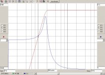
Here is the simulated response of my 3rd-order elliptical filter. The notch is generated by a Bainter filter, which here gives a -65 dB with no adjustment or matching of parts. It is a truly beautiful circuit; the notch depth depends only on the opamp gain, which does not drift. The opamp models used were TL072, on the basis that whatever opamp was finally used it would have more gain than that.

Last night I built one, using 5532s. With no tweaking whatever the measured notch depth is greater than 95 dB. What about yer twin-T now, eh? The Bainter has another advantage in that it uses only two precision capacitors rather than three. It's also very good at making highpass notches, which is what you need for a highpass ellptical filter.
It is bitterly ironic that in this application a notch depth of more 50 dB is not really required.
You can see in the plot that there is massive attenuation at 10Hz, but compared with a 3rd-order Butterworth (red line) the -3dB point is higher and so the passband is less flat.
What is the answer? A 4th-order elliptical filter, perhaps. Building one now.
I was thinking passive with buffer. Twin T is the best fileter I feel but hardest to make practical. A SVF could work I think. Adapted Rosen, Ti FilterPro is great freeware
Where can we find those 40dB in Ladegaard's paper (AES 1977) you are referring to?Since this only gives 21 dB atten at 10 Hz it is a long way from the 40dB I am looking for. (Derived from the B&K paper)
Hans
20 dB was alll I ever needed except for 78's. If I read this right - 87 dB total for an LP if 40 dB. 1925 78 - 30 dB.
A very interesting article, throwing some light on the underestimated importance and function of a pickup arm.
Swedish Analog TEchnologies - ARTICLES
Hans
Swedish Analog TEchnologies - ARTICLES
Hans
I calculate -21.16dB at 10Hz.DouglasSelf said:Since this only gives 21 dB atten at 10 Hz it is a long way from the 40dB I am looking for.A 6th Order Sallen-Key 15Hz HPF with Butterworth response would be -21.6dB @ 10Hz and -.2dB @20Hz.
I calculate -28.18dB at 10Hz. 10Hz is still near the corner frequency so you can't expect to see the 6dB/order improvement.Hmmm. If we've gone up two whole orders I would have thought that we should get more improvement than 6 dB at 10Hz. Is -27.5dB right?An 8th Order Sallen-Key 15Hz HPF with Butterworth response would be -27.5dB @ 10Hz and -.11dB @20Hz.
An 8th-order Butterworth is going to require some pretty precise components, and 8 big and expensive capacitors per channel.
I think that when the resonance of the tonearm+cart is high, this resonance amplifies stylus motion at 20 Hz in excess, allowing to accept a little attenuation (1 to 2 dB).
With my system, the resonance ( around 11 Hz) is nearly 20 dB peak and give excess gain of 2.6 dB at 20 Hz.
What I want to say is, depending of course of real resonance, this may allow a less high-order filter.
jacques
With my system, the resonance ( around 11 Hz) is nearly 20 dB peak and give excess gain of 2.6 dB at 20 Hz.
What I want to say is, depending of course of real resonance, this may allow a less high-order filter.
jacques
Holman, see AES paper below, gives on page 3 under "Infrasonic Response" the following information:
http://www.davidreaton.com/PDFs/Holman_AES_paper.pdf

Hans
http://www.davidreaton.com/PDFs/Holman_AES_paper.pdf
Hans
Where can we find those 40dB in Ladegaard's paper (AES 1977) you are referring to?
Hans
See Figure 10 (left) where the peak is 40 dB above the general groove noise.
I am not saying that 40 dB of suppression is essential; 30 dB would probably be fine. It is however a nice round number to aim at.
I wonder how the Townshend Rock turntable measured with the arm damping trough. Assuming the lp rotation is the cause, it should not have helped as it was stabilising the cartridge relative to the platter, not the record
OK, how about this:
Change all the 2U2 caps to 1U8 in an 8th order BW filter at 18.4 Fc. That gives -41.5dB at 10Hz, -0.94dB at 20Hz and keeps group delay less than 20mS for freqs 34Hz and above (less than 30mS for freqs 27Hz and above).
Change all the 2U2 caps to 1U8 in an 8th order BW filter at 18.4 Fc. That gives -41.5dB at 10Hz, -0.94dB at 20Hz and keeps group delay less than 20mS for freqs 34Hz and above (less than 30mS for freqs 27Hz and above).
Attachments
Caps of that size are going to be about a pound apiece, more if you go to polyprop to avoid distortion. 220nF seems to me more practical.All of the filter designs used 2U2 caps for simplicity, only the R values (and ratios) changed.
If there are no notches in the stopband, how can it be an elliptical filter? Surely your software has handed you a Chebychev?The results were from RFSIM99 (linear simulation), but I've built similar order filters (8th order ELP 300 Hz HPF) and the results were close to the simulations. There were no notch sections in the simulations.
I have written several articles about that. See the latest Linear Audio (Vol 11) where I compare E96 values with 2xE24 and 3xE24. The latter is much better for little more money. Resistors are cheap compared with caps.With the higher order filters, precision resistors are required to exactly meet the filter coefficients, but in practice (and simulation), rounding off to standard values (E24-E96) didn't make that much of a difference except in the output stage where the ratio of the grounded R:feedback R was quite high as in the 8th order Elliptical (560:1). Precise values can be obtained by series or parallel combinations of 1% values.
At what frequency does the errror fall to 0.1 dB? That is the criterion I have been using.The passband ripple was from 20Hz to ~100 Hz, flat after that. Perhaps with better resistor matching it could be reduced in the simulations; in practice, it seemed only the last stage was ultra-critical IIRC.
I still can't see that passband ripple could ever be acceptable.
No filter can predict the cutting lathe in general as they differ. Guys I have the AES patents on this. It's not simple. Solution with no real problem ? Ceramics were better in most ways. Alas no higher grade exist to tody at Denon 103 prices. The maths here is missinhg a defined set of datum points. I have no idea what they are if asking. I have seen the graphs and Q is the key.
You seem to be under the impression that disc warps are somehow put onto the disc by the cutter head, apparently deliberately.
Not so.
A very interesting article, throwing some light on the underestimated importance and function of a pickup arm.
Swedish Analog TEchnologies - ARTICLES
Hans
Thanks Hans, that is interesting. The idea that platters have to be hugely massive so they don't bounce up and down due to the warp forces is new to me.
I do not think I am convinced...
I think that when the resonance of the tonearm+cart is high, this resonance amplifies stylus motion at 20 Hz in excess, allowing to accept a little attenuation (1 to 2 dB).
With my system, the resonance ( around 11 Hz) is nearly 20 dB peak and give excess gain of 2.6 dB at 20 Hz.
What I want to say is, depending of course of real resonance, this may allow a less high-order filter.
jacques
The whole idea of using an elliptical filter with at least one stopband notch around 10 Hz is to keep the filter order down to a modest level.
I have designed 3rd, 4th order, (one notch) and 5th and 6th order (two notches) types and you need to go to 5th to get passband flatness superior to a 3rd-order 20Hz Butterworth. (which has been my default rumple filter for many years) To my mind 6th-order is about the practical limit of complexity.
The design process was not straightforward, but I believe that I have come up with 'official' elliptical filters.
Will publish more response curves when I get a moment.
Caps of that size are going to be about a pound apiece, more if you go to polyprop to avoid distortion. 220nF seems to me more practical.
You can download the spreadsheet, so you are free to try what ever series values suit your fancy. It might be prudent to use 220n to increase the input impedance as well.
If there are no notches in the stopband, how can it be an elliptical filter? Surely your software has handed you a Chebychev?
You are correct, it is Chebychev. Per the article posted by Hans, either one probably has to much phase distortion to be practical.
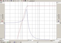
This shows the response of the 4th-order highpass elliptical filter with A0= 35 dB. The 10 Hz notch now has a higher Q and so is narrower. giving a more rapid rolloff, and this moves the -3dB point down from the 29.5 Hz of the 3rd-order filter to 26.2 Hz; a helpful improvement, but not 20 Hz. Below the notch the response again comes back up to -35 dB around 7 Hz, as expected, but then heads downwards forever at 12 dB/octave, giving much better rejection of VLF signals below 3 Hz than the 3rd-order filter.

- Status
- Not open for further replies.
- Home
- Source & Line
- Analogue Source
- What is the ideal conventional rumble filter?- Douglas Self