Did you make a new PCB?
Kaplaars. did you make your own JLH Headphone Clone PCB? I would like to build one, please share the design.😀
Kaplaars. did you make your own JLH Headphone Clone PCB? I would like to build one, please share the design.😀
Well... lazy as I am 😀 I have not designed the PCB myself but bought it via eBay instead 😉. However, I would personally not recommend to buy the blue JHL PCB unless you are willing to modify it a bit. With an offset of ~160mV without constant trimming it is not really practical for the long term unless you add a servo or output capacitor. What could probably help is matching the output transistors and mounting them onto one heatsink instead of two. The latter to minimise impact by thermal fluctuations between the devices. However, I have not tried this myself.
What ebay vendor did you use?
What's the name and WEB address of the vendor you used to obtain these
PCB's.Take care.😕
What's the name and WEB address of the vendor you used to obtain these
PCB's.Take care.😕
I bought the PCB from ebay vendor 'Minishow': JHL Class A Headphone Amplifier Pre Amp Preamplifier PCB | eBay Unfortunatelly there was no (mini)show included (I like the cars 😉), but hey for this amount of money that was probably too much to ask for anyway 😀.
There are also complete, even assembled kits on eBay. For example here: http://www.ebay.com/itm/Class-A-Headphone-Amplifier-Board-PRE-amp-kit-Dual-AC12-15V/111231806577?_trksid=p2047675.c100011.m1850&_trkparms=aid%3D222007%26algo%3DSIC.MBE%26ao%3D1%26asc%3D20140602152332%26meid%3D8dc1aa2e3ecf4b49a9aa821daf19d5c6%26pid%3D100011%26rk%3D6%26rkt%3D10%26mehot%3Dpp%26sd%3D130665846659. However, beware of fake components when ordering a complete kit. It is certainly a nice project and it sounds quite well. To make it better check this threat; in here are some nice, some highly recommended, modifications proposed.
There are also complete, even assembled kits on eBay. For example here: http://www.ebay.com/itm/Class-A-Headphone-Amplifier-Board-PRE-amp-kit-Dual-AC12-15V/111231806577?_trksid=p2047675.c100011.m1850&_trkparms=aid%3D222007%26algo%3DSIC.MBE%26ao%3D1%26asc%3D20140602152332%26meid%3D8dc1aa2e3ecf4b49a9aa821daf19d5c6%26pid%3D100011%26rk%3D6%26rkt%3D10%26mehot%3Dpp%26sd%3D130665846659. However, beware of fake components when ordering a complete kit. It is certainly a nice project and it sounds quite well. To make it better check this threat; in here are some nice, some highly recommended, modifications proposed.
Last edited:
mrsavage I got my finished kit from here
Enjoy in your hi-fi project, diy tube amp, amplifier diy, amp diy
They have PCBs available too
PCB : Enjoy in your hi-fi project, diy tube amp, amplifier diy, amp diy
Enjoy in your hi-fi project, diy tube amp, amplifier diy, amp diy
They have PCBs available too
PCB : Enjoy in your hi-fi project, diy tube amp, amplifier diy, amp diy
See Thread Number 580
The PCB I'm talking about is shown in the JLH Headphone Amp, Thread Number 580. This is the one I'm looking for. It might not be a JLH Headphone Amp.
😕
The PCB I'm talking about is shown in the JLH Headphone Amp, Thread Number 580. This is the one I'm looking for. It might not be a JLH Headphone Amp.
😕
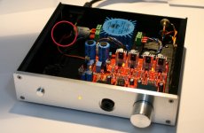
That is not the JLH. That is the Beyerdynamic A1 clone. It think it is this one
Assembled board E3 class A headphone amplifier clone A1 - $38.80 : Enjoy in your hi-fi project, diy tube amp, amplifier diy, amp diy
Assembled board E3 class A headphone amplifier clone A1 - $38.80 : Enjoy in your hi-fi project, diy tube amp, amplifier diy, amp diy
....The other head amp is a clone of the Beyerdynamic A1 circuit....
Thus, a different amp than the JHL 😎. Bought the PCB from Jims Audio: High-end stereo headphone amplifier w/protection circuitry A1 PCB 1piece ! | eBay
John Linsley Hood = JLH not JHL .... It is even spelled wrong on the front of your amp, Kaplaars.
Last edited:
@Dearchap, near the power socket. If you look carefull at the A1 picture you can see two red wires, one is connected to the amplifier GND (just between the two PSU capacitors), the other one to mains earth, both meeting at one point at the chassis. See attachment. For the JLH I did something similar. However, this is not shown on the pictures (at that time I still had to find the best null point).
@JP Haha, you are absolutely right! How could I have missed that 😀
@JP Haha, you are absolutely right! How could I have missed that 😀
Attachments
Kaplaar excellent photo, Thanks. What point in the chassis was this ? Is it the rail like thing where chassis screws go in or did you drill a new hole ?
For the A1 I attached the earth pin to the chassis via a circular cable shoe. This cable shoe is attached via one of the screws and that in turn attachs one of the aluminum feets to the chassis. Between is a lock washer for a better connection between cable shoe and chassis (since the chassis is anodised). So basically the earth pin is attached to the bottom plate at the left side when looking from the front (very near the ferrite clamp). This way I did not had to drill a separate hole since there was already a connection with a very low resistance. For the JLH I attached the earth pin to one of the screws that sequres the IEC inlet. Rod Elliot has written a nice article about how a good connection could be established: Earthing (Grounding) Your Hi-Fi - Tricks and Techniques
Btw, sometimes people use the bolt that secures the toroidal transformer for attaching the earth cable. This is wrong because this way you basically create a shorted winding, which impacts the efficiency of your transformer or could even damage it.
Btw, sometimes people use the bolt that secures the toroidal transformer for attaching the earth cable. This is wrong because this way you basically create a shorted winding, which impacts the efficiency of your transformer or could even damage it.
Last edited:
@JP Haha, you are absolutely right! How could I have missed that 😀
Steer clear of the jonkos 🙂
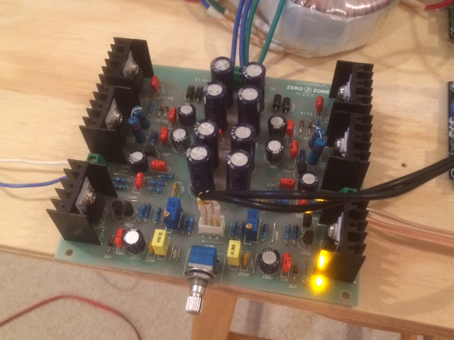
I just built one from Aliexpress and really like the sound. It can even double as a fleawatt speaker amp. Here it is powering a 91dB 3FE22 in a bass reflex box.
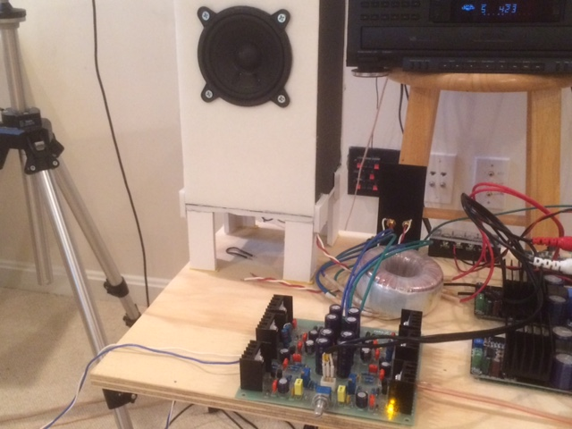
I am using an Antek 15v 25VA transformer and switched the 5.1ohm 1/4w for a 4.4ohm 4watt resistor.
DC offset seems to stabilize writhing 20mV depending on ambient temperature. I am wondering if output caps really needed. Just tested with my MDR-V6's and it sounds like I have never heard it before. A lot more resolution and detail with great bass punch.
All in all, a great deal for a $20 amp - just need a box now.
For low frequencies, that assumption is correct. At higher freqs that are relevant to stability, the parallel R-C comes in. I'd suggest modifying R5 only.
You may be able to do without the parallel R-C actually, at least I found that stability in simulation rather improved that way. A set of capacitor values to annoy the output with (1n, 2n2, 10n, 22n, 47n) and a scope may come in handy.
You may be able to do without the parallel R-C actually, at least I found that stability in simulation rather improved that way. A set of capacitor values to annoy the output with (1n, 2n2, 10n, 22n, 47n) and a scope may come in handy.
For low frequencies, that assumption is correct. At higher freqs that are relevant to stability, the parallel R-C comes in. I'd suggest modifying R5 only.
You may be able to do without the parallel R-C actually, at least I found that stability in simulation rather improved that way. A set of capacitor values to annoy the output with (1n, 2n2, 10n, 22n, 47n) and a scope may come in handy.
Would it be okay to use 2K for R5?
So leave both C11 and R12(I think that's R12 that's in series with C11) off the board?
I don't own a scope. What do you mean by the different capacitors to annoy the output with?
Thanks...
Regarding controlling the offset on the outputs thru time: Could it be minimized if we bolt the transistors on a bigger heatsink (for example bending the transistors legs and bolting them to the case bottom with insulators and good thermal paste, of course) and put the 1N4148 diodes very close to them or even touching the heatsink?
Or is this too much hassle for too little improvement?
I'd really like to avoid servos and capacitors on output if it's possible.
Or is this too much hassle for too little improvement?
I'd really like to avoid servos and capacitors on output if it's possible.
Last edited:
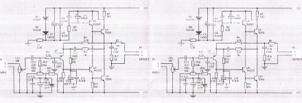
^ You are referring to D1 and D2 on the JLH Circuit 1 schematic, I guess? I do think it would help if you thermally couple those plus Q1, Q3 and Q4, but getting a near-zero temperature coefficient would require a bit more thought.
Incidentally, I don't think you can even get to a zero offset with just these two diodes, the circuit ammel68 posted doesn't use a 2.7V zener for no reason. Which would have a different tempco than 4-5 Si diodes or transistor B-E junctions, but that's another matter...
You can assume voltage drop from the base of Q4 to the output to be about 3 B-E junctions. Why? Well, if we neglect base currents for a while, the voltage over R4 is set by Vbe(Q3) + Vbe(Q1), and R4 is where (approximately) all of Q4's collector current flows through. Said collector current is sourced from the output via R7, another resistor of same value. So the voltage over R4 is mirrored over R7. The trusty LM386 uses a similar trick. Which incidentally also is why the advice I gave to ammel68 earlier is not entirely without its problems (you would have to readjust offset at the very least), and sure enough I modified the value of R5 (R17 in the schematic he gave), using 1k2 rather than 470R.
Now in real life of course, Q3's base will be a bit thirsty and drain some current away from R4. I simulated using a 2N5551 model, and that one consumed 71 µA (at ~8.1 mA Ic), leaving 309 µA for R4. So the drop over R7 would actually be somewhat higher, and Ib(Q3)(T) may also figure in to some degree.
This whole shebang of more or less 3 B-E junctions wants to be offset by a voltage on Q4's base. For this we have our offset voltage source of either a bunch of forward-biased diodes or zener or whatever (with associated tempco), reduced by a resistor divider, minus some offset primarily a result of Q4 base current through R1.
So now you've got to calculate the tempco on the voltages on both sides and make it equal as far as possible. Then thermally couple everything nicely and you should have a fairly stable output DC offset.
You can probably see why some people would prefer a dumb servo instead...
A scope is quite handy. You don't need anything too fancy, a 10-20 MHz analog job ought to be fine. Mine is actually older than me and soon approaching its 40th birthday. I guess a decent probe would be nice.
Incidentally, I don't think you can even get to a zero offset with just these two diodes, the circuit ammel68 posted doesn't use a 2.7V zener for no reason. Which would have a different tempco than 4-5 Si diodes or transistor B-E junctions, but that's another matter...
You can assume voltage drop from the base of Q4 to the output to be about 3 B-E junctions. Why? Well, if we neglect base currents for a while, the voltage over R4 is set by Vbe(Q3) + Vbe(Q1), and R4 is where (approximately) all of Q4's collector current flows through. Said collector current is sourced from the output via R7, another resistor of same value. So the voltage over R4 is mirrored over R7. The trusty LM386 uses a similar trick. Which incidentally also is why the advice I gave to ammel68 earlier is not entirely without its problems (you would have to readjust offset at the very least), and sure enough I modified the value of R5 (R17 in the schematic he gave), using 1k2 rather than 470R.
Now in real life of course, Q3's base will be a bit thirsty and drain some current away from R4. I simulated using a 2N5551 model, and that one consumed 71 µA (at ~8.1 mA Ic), leaving 309 µA for R4. So the drop over R7 would actually be somewhat higher, and Ib(Q3)(T) may also figure in to some degree.
This whole shebang of more or less 3 B-E junctions wants to be offset by a voltage on Q4's base. For this we have our offset voltage source of either a bunch of forward-biased diodes or zener or whatever (with associated tempco), reduced by a resistor divider, minus some offset primarily a result of Q4 base current through R1.
So now you've got to calculate the tempco on the voltages on both sides and make it equal as far as possible. Then thermally couple everything nicely and you should have a fairly stable output DC offset.
You can probably see why some people would prefer a dumb servo instead...
In light of the above, better modify R17 instead, 1k2 seems about right in this case, too. And yes, C11/R12 were the ones I meant.Would it be okay to use 2K for R5?
So leave both C11 and R12(I think that's R12 that's in series with C11) off the board?
Capacitive loading, quite literally. Hang 'em on the output and see whether the circuit grossly misbehaves (oscillates). A typical 3 m headphone cable may exhibit about 1 nF, so it must be able to drive that, so to be safe I'd say 10 nF minimum, better 47 nF.I don't own a scope. What do you mean by the different capacitors to annoy the output with?
A scope is quite handy. You don't need anything too fancy, a 10-20 MHz analog job ought to be fine. Mine is actually older than me and soon approaching its 40th birthday. I guess a decent probe would be nice.
Last edited:
- Home
- Amplifiers
- Headphone Systems
- JLH Headphone Amp