I am trying to add an Arduino microprocessor to a power amplifier to display internal temperature and power of output at the speaker terminals on an LCD display.
However, I am having some trouble determining the best way to measure the voltage and current due to them being AC signals. Here is my best guess at a method, let me know if it sounds reasonable:
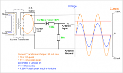
Use a biasing circuit to make sure all AC signals are translated into a 0-5V measurement range for all operating conditions. Was going to use something such as this: https://openenergymonitor.org/emon/buildingblocks/ct-sensors-interface
I would then convert this measurement to a value by saying:
VALUE=abs((INPUT-2.5))*scalingfactor
(where scalingfactor is the correction factor to convert measurement voltage back to "real" V or A)
Calculating an RMS value for my power calculation is where I am struggling. Is it reasonable to simply collect a good amount of data points (say 20) over a period of 0.25 seconds, store them in an array, square each value and then divide out the number of samples and take the square root?
RMS=sqrt((sum(VALUE*2, i=0..20))/i)
(where i is the number of samples)
Let me know if I am totally confused or on the right track 🙂
However, I am having some trouble determining the best way to measure the voltage and current due to them being AC signals. Here is my best guess at a method, let me know if it sounds reasonable:
Use a biasing circuit to make sure all AC signals are translated into a 0-5V measurement range for all operating conditions. Was going to use something such as this: https://openenergymonitor.org/emon/buildingblocks/ct-sensors-interface
I would then convert this measurement to a value by saying:
VALUE=abs((INPUT-2.5))*scalingfactor
(where scalingfactor is the correction factor to convert measurement voltage back to "real" V or A)
Calculating an RMS value for my power calculation is where I am struggling. Is it reasonable to simply collect a good amount of data points (say 20) over a period of 0.25 seconds, store them in an array, square each value and then divide out the number of samples and take the square root?
RMS=sqrt((sum(VALUE*2, i=0..20))/i)
(where i is the number of samples)
Let me know if I am totally confused or on the right track 🙂
Haven't used arduino for signal processing. I think arduino is pretty slow, maybe 5-10kS/s, you would want at least 40kS/s or you will only read power data below half the sampling rate and could have aliasing issues.
Google for 'RMS to DC converter' - adding arduino to that search reveals quite a few results, but I haven't read any 😉
Google for 'RMS to DC converter' - adding arduino to that search reveals quite a few results, but I haven't read any 😉
I am trying to add an Arduino microprocessor to a power amplifier to display internal temperature and power of output at the speaker terminals on an LCD display.
However, I am having some trouble determining the best way to measure the voltage and current due to them being AC signals. Here is my best guess at a method, let me know if it sounds reasonable:
Use a biasing circuit to make sure all AC signals are translated into a 0-5V measurement range for all operating conditions. Was going to use something such as this: https://openenergymonitor.org/emon/buildingblocks/ct-sensors-interface
I would then convert this measurement to a value by saying:
VALUE=abs((INPUT-2.5))*scalingfactor
(where scalingfactor is the correction factor to convert measurement voltage back to "real" V or A)
Calculating an RMS value for my power calculation is where I am struggling. Is it reasonable to simply collect a good amount of data points (say 20) over a period of 0.25 seconds, store them in an array, square each value and then divide out the number of samples and take the square root?
RMS=sqrt((sum(VALUE*2, i=0..20))/i)
(where i is the number of samples)
Let me know if I am totally confused or on the right track 🙂
I think you would integrated each area under two consecutive samples, no?
BTW I have a similar project where I use an AD536 AC to RMS converter feeding into a PIC ADC pin. Works like a charm.
Jan
Last edited:
Rectify the signal to get DC.
Will I not lose a big chunk of my signal due to the forward voltage on the rectifiers?
Haven't used arduino for signal processing. I think arduino is pretty slow, maybe 5-10kS/s, you would want at least 40kS/s or you will only read power data below half the sampling rate and could have aliasing issues.
Google for 'RMS to DC converter' - adding arduino to that search reveals quite a few results, but I haven't read any 😉
Thanks, yep I am aware of the aliasing issues. But I am not looking to adequately sample the signal, only average out the amplitude of the signal for a rough calculation of output power.
I think you would integrated each area under two consecutive samples, no?
BTW I have a similar project where I use an AD536 AC to RMS converter feeding into a PIC ADC pin. Works like a charm.
Jan
That AD536 looks ideal, sadly at the cost though I'd be spending over $100 for them though for the number of inputs I was hoping to use.
That AD536 looks ideal, sadly at the cost though I'd be spending over $100 for them though for the number of inputs I was hoping to use.
You could mux the input.
https://en.wikipedia.org/wiki/True_RMS_converter#Analog_electronic_converters
There is a way to make a "precision diode" (no forward voltage) using an op amp and a diode, and you can buffer the circuit to keep it from loading the source.
http://forum.allaboutcircuits.com/threads/good-full-wave-precision-rectifier.64943/
There is a way to make a "precision diode" (no forward voltage) using an op amp and a diode, and you can buffer the circuit to keep it from loading the source.
http://forum.allaboutcircuits.com/threads/good-full-wave-precision-rectifier.64943/
Last edited:
Find an opamp circuit book or even at the end of some opamp data sheets and you will find a Rams detector built with opamps. Or Google opamp Rams detector.
for true RMS you have to detect the zero cross point I believe, for mains this can be a bit of fun, for a clean sine wave not so bad.
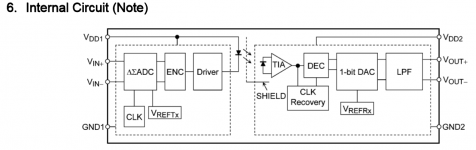
As an alternative to current transformers -
TLP7920 - TOSHIBA - OPTOCOUPLER, ISOLATED, 5KV, DIP-8 | Farnell element14
I think we will be seeing a lot more of these soon.
TLP7920 - TOSHIBA - OPTOCOUPLER, ISOLATED, 5KV, DIP-8 | Farnell element14
I think we will be seeing a lot more of these soon.
Aliasing will not be a problem as you are not interested in reconstructing the signal, merely measuring how big it is. You can sample as often or as slowly as you like.Ron E said:Haven't used arduino for signal processing. I think arduino is pretty slow, maybe 5-10kS/s, you would want at least 40kS/s or you will only read power data below half the sampling rate and could have aliasing issues.
I assume that the 'abs' indeanoUK said:Rectify the signal to get DC.
VALUE=abs((INPUT-2.5))*scalingfactor
does the rectification.
Wiggle8 said:Calculating an RMS value for my power calculation is where I am struggling. Is it reasonable to simply collect a good amount of data points (say 20) over a period of 0.25 seconds, store them in an array, square each value and then divide out the number of samples and take the square root?
RMS=sqrt((sum(VALUE*2, i=0..20))/i)
(where i is the number of samples)
That would work. However, you might want to maintain some sort of moving average or low pass, so you get a smoother change. To 'low pass' over 20 samples:
initialise:
RMSLP =0.0
loop:
get VALUE
RMS = sqrt(VALUE^2)
RMSLP = 0.95*RMSLP + 0.05*RMS
display RMSLP
goto loop
Measuring amp power is more involved. i did it digitally and the first effort was a disaster. First the power is the product of volts and amps. You can't just measure the volts and the amps. You need to measure the instantaneous power (volt X amps} and then pick an averaging time. You will also need to decide on attack times and decay times. And a digital display will be very hard to read if those are too short. (I got a patent on that, not my best work but it looks good in the portfolio).
HP has a discussion on sampling AC voltage accurately in the writeup on the HP (Agilent Keysight) 3458 Page 15 here http://www.hpl.hp.com/hpjournal/pdfs/IssuePDFs/1989-04.pdf (25 years later its still the most accurate lab DVM.) However you will need to sample voltage and current simultaneously and then do a lot of math.
Doing this gets some interesting and unexpected power numbers with speakers and their changing impedance. Its also possible to show instantaneous impedance.
Thanks everyone for the input, clearly this is requiring a bit more work than I had expected.
Currently I have test code running that generates fake sensor values but performs smoothing by collecting 30 samples over a 400 millisecond period.
As 1audio mentioned, I needed to add appropriate delay in the program so that the screen does not go into a frenzy trying to update so quickly. Obviously I won't be able to capture high instantaneous power peaks but if I could average out levels on a half second basis I would be quite happy.
Part of me is considering a little bit of a cheat. Placing the CT instead on the DC input to the amplifier. This measurement should be more stable and easy to measure. Off course it will not be equal to the actual speaker output but could still be a useful metric.
On a side note I've got the program measuring temperature quite stably and have also got the LCD basically working. I also have an input selection function by allowing a microswitch input and an output which will be used to select inputs by way of a relay.
Most CT'S are AC only so not useful on the DC supply. The DC will saturate the core really distorting the output. There are Hall effect CT'S but they have drift problems. There are some chips designed for monitoring current through a resistor with high common mode.
Fast Peak and long decay gave the best results. It still will look like a slot machine in operation.
Maybe you should drive an analog meter with the computed output. I wanted to but it was not an option.
Sent from my SGH-M919 using Tapatalk
Fast Peak and long decay gave the best results. It still will look like a slot machine in operation.
Maybe you should drive an analog meter with the computed output. I wanted to but it was not an option.
Sent from my SGH-M919 using Tapatalk
- Status
- Not open for further replies.
- Home
- Design & Build
- Software Tools
- How to sample AC signal for RMS level calculation