I've got both the core type and Hall Effect type CTs coming to play with. I'll have to experiment to see if I can get satisfactory results from either. The analog meter idea is a good one too. I'm really trying to develop my programming skills on this so interested in solving some problems even if they have better solutions in a different domain though.
How serious are the drift issues with the Hall Effect CTs? I am not looking for supreme accuracy here just more general trending.
On the Tek or the Fluke probes it's enough to need adjustment everytime you use one and usually an hour later.
The useful dynamic range needed is the biggest problem. Normal listening levels may be .1 -2 Watts. On a linear scale for a 100W amp that's invisible.
Nonlinear scaling is difficult for dynamic systems. Using an Audio adc could give the necessary range but magnifies the difficulty a lot (was too expensive for my effort).
Sent from my SGH-M919 using Tapatalk
Thanks for the insight, looks like a tricky little problem I've bitten off here.
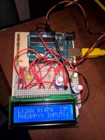
Regardless if I can get a good power measurement I intend to march forward. Other diagnostics could make due (thinking of showing both rail voltages for example). Quite excited to have a custom display for my amplifier. Attached is my current prototype. I've got the screen going with a larger 4x20 display in the mail. The left channel power reading is being created with a pot input for now, and right channel is just from a random number generation. The temperature is live and working (in Celsius, and yes that reading is accurate in my chilly unheated basement 🙂 ). Also have two switches to control two other features. One will be to turn off or on an optional pre-amp section and the other is to select from one of two sets of RCA inputs. Currently those outputs are indicated with the yellow and green LEDs but ultimately those signals will be sent to relays. As well, the pushbutton microswitches will be swapped out for toggle type on the final amp.
Regardless if I can get a good power measurement I intend to march forward. Other diagnostics could make due (thinking of showing both rail voltages for example). Quite excited to have a custom display for my amplifier. Attached is my current prototype. I've got the screen going with a larger 4x20 display in the mail. The left channel power reading is being created with a pot input for now, and right channel is just from a random number generation. The temperature is live and working (in Celsius, and yes that reading is accurate in my chilly unheated basement 🙂 ). Also have two switches to control two other features. One will be to turn off or on an optional pre-amp section and the other is to select from one of two sets of RCA inputs. Currently those outputs are indicated with the yellow and green LEDs but ultimately those signals will be sent to relays. As well, the pushbutton microswitches will be swapped out for toggle type on the final amp.
Attachments
Last edited:
I am currently working on a PIC based amplifier peak power meter.
Rather than try to integrate the signal I have just taken the peak voltage and used that to calculate the peak power.
Then I multiply it by 0.707 to get RMS value.
Rather than try to integrate the signal I have just taken the peak voltage and used that to calculate the peak power.
Then I multiply it by 0.707 to get RMS value.
Last edited:
Thanks for the insight, looks like a tricky little problem I've bitten off here.
Regardless if I can get a good power measurement I intend to march forward. Other diagnostics could make due (thinking of showing both rail voltages for example). Quite excited to have a custom display for my amplifier. Attached is my current prototype. I've got the screen going with a larger 4x20 display in the mail. The left channel power reading is being created with a pot input for now, and right channel is just from a random number generation. The temperature is live and working (in Celsius, and yes that reading is accurate in my chilly unheated basement 🙂 ). Also have two switches to control two other features. One will be to turn off or on an optional pre-amp section and the other is to select from one of two sets of RCA inputs. Currently those outputs are indicated with the yellow and green LEDs but ultimately those signals will be sent to relays. As well, the pushbutton microswitches will be swapped out for toggle type on the final amp.
You should have fun with the project. My first amp (over 40 years ago) had a microcoded processor (real microprocessors were not available beyond the 4004) and readout on the front all run from a single touch button. It monitored the input and output for certain conditions. For example it would not power up if the input had significant signal or DC (no scary noises on turn on) as well as shutdown if the output got weird. Back then I used the HP Alphanumeric LED modules and announced what was wrong. For level and slew rate (big issue then) I used bar graphs. Not enough computing power or adequate ADC's to do anything like your doing. Back then I was speculating on a scheme to detect the type of music playing and shut down for certain types. You have lots of flexibility to do interesting things.
BTW the patent on the metering is https://www.google.com/patents/US8401197. Don't worry about it. Its all ancient history and they aren't making amps any more.
- Status
- Not open for further replies.