Is there some sort of simple electronic HIGHPASS filter that could eliminate those signals being passed along to the speakers? I'm thinking of something that would eliminate sounds below 14-16 Hz.
I already posted info on this issue in some detail in post 580. http://www.diyaudio.com/forums/subw...binet-16-hz-organ-speaker-58.html#post4660566
It's not a super simple process because the Inuke was not designed to do this but it's possible and it's not that hard.
FYI, you can use the DCX to high pass lower than 20Hz. There are two means to get an effective lower frequency high pass filter. If you look at both 12 & 18dB/octave Bessel filters, you will see the sharper roll off is in fact a good bit lower than the nominal Fc. Addition of 1-2 PEQ's makes a lower effective XO pretty easy. The other, more straight forward option is to use a Butterworth or LR with a simple 12dB/Oct Low Shelving filter (would have to check the "Q" of the shelf to see if or LR matches best). In simple terms, you are basically applying a Linkwitz Transform to the high pass filter. Works just fine within reason. There is probably some point where the cut and boost exceed the working range of the DSP math, but I've done this in practice a few times with good results.
WmAX--Well, that's actually quite easy. The DCX does not have ability to set filters below 20Hz. While this may seem to high, it's not really. You can easily extend the actual filter by for example setting high pass filter to 20Hz, 2nd order, Butterworth. Now add a single parameteric band at 20Hz in the EQ section on the unit, set to Q of 1.5 and gain of +4 dB. This will counteract and extend the roll off, giving you an effective roll off on the 13w7 of -3dB around 17Hz and -6db around 14hz, with rapid roll off after this; exactly what you want with this 10 cubic foot cabinet tuned to about 16Hz to prevent excessive excursion under this tuning frequency.
If you want something simpler that comes with instructions you could purchase a standalone unit like mini dsp, but you will probably find that it's not a whole lot easier (assuming you can get some detailed step by step instructions for setting up an Inuke hpf at your desired frequency response). If you wanted an easy answer you should have bought a product that was designed to do what you want it to do.
At some point you have to take a step outside of this thread and do some research (there's lots of info on this issue out there) or ask for help from experts in the field. Those experts for Inuke stuff are at avs forum, maybe even in this forum, people that are here but not reading this thread. Did you even read post 580? It's unclear because you are asking the same question again after being given the answer.
If I had an Inuke I'm sure the info in the two quotes above would be more than enough information to get me started on finding the perfect settings, but since I don't have an Inuke and I'm not willing to troll for info on this subject without being able to confirm the info before passing it on, this is as far as i'm going to go on the Inuke hpf issue.
Last edited:
JAG
Here's the post I believe you meant me to read in the link you included. Thanks! This is for the Behringer DCX2496, but I suspect the same process should/would work for the iNuke3000DSP. I'll try it out in some of my experimenting.
And FYI - I am doing research outside this thread. But I appreciate your efforts to point me in the right general direction.
Bach On
Illka--I used the Behringer DCX2496, but it actually doesn't have a 15 Hz HP filter. I used its lowest, 20 Hz (12 dB/octave Butterworth), setting instead but used a wide boost (bandpass filter) around 20 Hz, so effectively the filter was around 15 Hz. I couldn't have gone much lower with the DCX2496
Seaton--Hi Ilkka, Awesome results on this sub and of course the data on all the others. FYI, you can use the DCX to high pass lower than 20Hz. There are two means to get an effective lower frequency high pass filter. If you look at both 12 & 18dB/octave Bessel filters, you will see the sharper roll off is in fact a good bit lower than the nominal Fc. Addition of 1-2 PEQ's makes a lower effective XO pretty easy. The other, more straight forward option is to use a Butterworth or LR with a simple 12dB/Oct Low Shelving filter (would have to check the "Q" of the shelf to see if or LR matches best). In simple terms, you are basically applying a Linkwitz Transform to the high pass filter. Works just fine within reason. There is probably some point where the cut and boost exceed the working range of the DSP math, but I've done this in practice a few times with good results.
VAS--you can't ( as far as i can tell ) set any filter to lower than 20 hz on either DCX or DEQ however what you can do is:
1 - set SSF to 20 hz
2 - apply parametric boost at 20 hz at the same time
3 - apply CUT at around 25 hz or so
by playing with the parameters of these 3 filters you can get 2 and 3 to mostly cancel each other out above 20 hz but their net effect will be significant boost below 20 hz
this boost below 20 hz will interact with 20 hz SSF and the net result will be that the boost will largely get cancelled and SSF will shift down in frequency.
how much lower you would be able to push the SSF frequency would depend on the order of the highpass. you would be able to push a 6db/oct highpass much lower than a 48db/oct highpass.
WmAX--Well, that's actually quite easy. The DCX does not have ability to set filters below 20Hz. While this may seem to high, it's not really. You can easily extend the actual filter by for example setting high pass filter to 20Hz, 2nd order, Butterworth. Now add a single parameteric band at 20Hz in the EQ section on the unit, set to Q of 1.5 and gain of +4 dB. This will counteract and extend the roll off, giving you an effective roll off on the 13w7 of -3dB around 17Hz and -6db around 14hz, with rapid roll off after this; exactly what you want with this 10 cubic foot cabinet tuned to about 16Hz to prevent excessive excursion under this tuning frequency.
Ok, here's a few pics to show what you are trying to do and how it works.
First you need a target filter to protect the driver and you need to know what that target filter looks like. Let's pick a random target of 14 hz 4th order Butterworth high pass filter (boxed in red in the inputs section to the left of the graph). The filter shape looks like this graph.
Now since we know there's no way to set a 14 hz Butterworth high pass filter in the Inuke dsp software we need to figure out what settings are available that we can use to make an approximation of this target filter.
It appears that if I use the active crossover module to apply a 2nd order Butterworth crossover at 20 hz, and then apply a 3 db parametric eq boost at 20 hz with q = 1.5 (all entered filter parameters boxed in green), we get a filter transfer function roughly similar to the original target filter, the 14 hz BW 4th order high pass filter.
I downloaded the Inuke DSP software and it will allow you to enter a 2nd order 20 hz BW high pass and a 3 db 20 hz parametric eq boost with q = 1.5, so it appears that you can indeed get a target filter roughly equal to 14 hz 4th order BW high pass using settings that the Behringer does allow.
A couple of notes - first you could get something a lot closer to the target, my filter transfer function is a rough match, it's flat down to 20 hz and 12 db down a 10 hz, same as the target, but it's not exactly the same. If you mess around for more than 5 minutes playing with the active crossover filter type and parametric eq boost settings you could get a lot better closer match, although it hardly matters. The point is I only spent 5 minutes on this so it's only a rough match between the target filter and the actual filter transfer function.
Second, although I think I did everything right here, this is the first time I've ever used the active crossover portion of this spreadsheet so it's possible I've made errors. Caveat emptor. I don't think so, but even if I did, this is still a good explanation of what you are trying to achieve and how to go about doing it.
First you need a target filter to protect the driver and you need to know what that target filter looks like. Let's pick a random target of 14 hz 4th order Butterworth high pass filter (boxed in red in the inputs section to the left of the graph). The filter shape looks like this graph.
An externally hosted image should be here but it was not working when we last tested it.
Now since we know there's no way to set a 14 hz Butterworth high pass filter in the Inuke dsp software we need to figure out what settings are available that we can use to make an approximation of this target filter.
It appears that if I use the active crossover module to apply a 2nd order Butterworth crossover at 20 hz, and then apply a 3 db parametric eq boost at 20 hz with q = 1.5 (all entered filter parameters boxed in green), we get a filter transfer function roughly similar to the original target filter, the 14 hz BW 4th order high pass filter.
An externally hosted image should be here but it was not working when we last tested it.
I downloaded the Inuke DSP software and it will allow you to enter a 2nd order 20 hz BW high pass and a 3 db 20 hz parametric eq boost with q = 1.5, so it appears that you can indeed get a target filter roughly equal to 14 hz 4th order BW high pass using settings that the Behringer does allow.
A couple of notes - first you could get something a lot closer to the target, my filter transfer function is a rough match, it's flat down to 20 hz and 12 db down a 10 hz, same as the target, but it's not exactly the same. If you mess around for more than 5 minutes playing with the active crossover filter type and parametric eq boost settings you could get a lot better closer match, although it hardly matters. The point is I only spent 5 minutes on this so it's only a rough match between the target filter and the actual filter transfer function.
Second, although I think I did everything right here, this is the first time I've ever used the active crossover portion of this spreadsheet so it's possible I've made errors. Caveat emptor. I don't think so, but even if I did, this is still a good explanation of what you are trying to achieve and how to go about doing it.
That's how to do it. But what can with do with that information?
NOT MUCH.
Until you verify the tuning of your box, compare it to tb46's design sim and figure out what target filter you ACTUALLY need to protect the driver.
To verify the tuning you ideally should set all gear in the signal path to flat (no notelevel Artisan eq, no dsp or eq of any kind anywhere in the signal path) and test to find out your ACTUAL box tuning.
When that is done, it can be compared to the design sim for the box and we can figure out what target high pass filter you actually need. Then we can figure out the settings in the Inuke DSP software that will replicate that target filter.
As you can see, I've roughly replicated a 14 hz 4th order BW filter with a simple high pass and one band of parametric eq that can be entered into the Inuke DSP software.
To get a better match or a lower frequency high pass filter we might need to play all kinds of games with the Inuke DSP, maybe even playing with shelf filters or Linkwitz transform to get an actual Inuke setting that can replicate a target filter accurately.
But this is stuff for way down the line. You've given no indication yet that you have set all components in the signal chain to output flat response and you have not verified the box tuning. You haven't even looked at the signal and clip lights on the amp to figure out if you are getting anywhere near enough signal.
I've already gone further now than I said I was going to wrt the Inuke DSP high pass filter settings. And at this point I'm really not going a step further until you at least get the very basics out of the way, like setting everything in your signal chain to flat, verifying box tuning and looking at your signal and clip lights to find out what's actually going on.
JAG,
Thanks for going beyond the call of duty. You've often done that for me - and for many others. I DO APPRECIATE YOUR CONSIDERABLE EFFORTS. I also know that you do so freely.
Bach On
Thanks for going beyond the call of duty. You've often done that for me - and for many others. I DO APPRECIATE YOUR CONSIDERABLE EFFORTS. I also know that you do so freely.
Bach On
To start, you just want to know (1) what is the frequency spectrum (RTA) of your lowest note and (2) does it maintain that profile (which should look sort of like the picture I posted from St. John the Devine, a fundamental and scaled partials) to the end of electronic chain.
If you are sure you can make the midi thingy reproduce the same output profile as your lowest pedal, that's just fine. But otherwise, I'd look for a sandbag. BTW, the loudness of that sustained note is probably* of no importance for these tests, so maybe a sandbag or heavy Bible on the pedal is all you need.
Creating these two RTA profiles takes seconds, done with gear you have and mostly understand, and requires no calibration.
If the terminal profile looks OK, then your next problem is ensuring signal levels are high enough. But fixing that is trivial, so no need to fuss about it now.
Ben
*unless your organ software is smarter than I give it credit for being
Last edited:
JAG,
Thanks for going beyond the call of duty. You've often done that for me - and for many others. I DO APPRECIATE YOUR CONSIDERABLE EFFORTS. I also know that you do so freely.
Bach On
If we get lucky and this can be accomplished through a simple hpf and one or two bands of parametric eq then this can all be done in Hornresp and the settings from Hornresp can be directly entered into the Inuke. But the actual real cab tuning should be determined first.
To start, you just want to know (1) what is the frequency spectrum (RTA) of your lowest note and (2) does it maintain that profile (which should look sort of like the picture I posted from St. John the Devine) to the end of electronic chain.
With any luck OP's signal won't look anything like any picture you posted, hopefully there's some actual strong low bass.
Creating these two RTA profiles takes seconds, done with gear you have and mostly understand, and requires no calibration.
You said his first measurement was garbage, now you say he understands the gear. Which is is? You can't have it both ways. Either he understands the gear (which means the first measurement was good) or he doesn't (which means the first measurement was bad).
If the terminal profile looks OK, then your next problem is ensuring signal levels are high enough. But fixing that is trivial, so no need to fuss about it now.
B.
Fixing low signal level is trivial for sure, but it might require adding another component (DI box) to the signal chain which could very well change the frequency response, so the signal level absolutely should be fixed before any measurements of anything are taken.
Your constant insistence that there is no low bass coming out of the Artisan and that cumulative low frequency roll off from the devices in the signal chain (some which aren't even in the chain yet) doesn't matter is going to cause problems in the long run if your advice is followed.
Last edited:
Bach, I had a thought when reading the last couple days postings. When you ran the RTA, was it actually reading the output from the Artisan, or was it reading silence? Knowing you have to run from the keyboard to the electronics, and can't be in both places, perhaps better to have your laptop record the sounds instead of trying to capture them "real time", and then analyze the recording? What I saw looked a lot like white noise, not an organ tone....
I would be strongly tempted to do this:
Install Audacity. It's free, and quite easy to use.
Set up to record on your laptop.
Start recording.
Walk to your keyboard
Play the pedal tones, one at a time.
Walk to the laptop and stop the recording.
Save the file and post it where we can get it to analyze.....
This is a pretty good idea, and what I recommended a couple of days ago.
Set all levels to flat in all components.
Record a single 16 hz note as a WAV file.
Analyze it with Audacity.
The benefit to this is that you can actually listen to the recorded file and verify what you are actually measuring.
Like I've been saying, it's impossible to even guess if the first recording was accurate or not, it certainly doesn't look like what you would expect to see. If you had a recording of the note you could listen to it AND analyze it and there would be no question about what you are seeing in the measurement.
Not sure if you can analyze a WAV file in REW (I don't have it installed right now) but that might be a possibility too.
You can always analyze a recorded sound... And play it back. If REW won't do it, there are certainly other tools. At a minimum, you will know exactly what you are analyzing, which we don't at present.
+1. Smart. REW does it fine too and communicates results clearly.Start recording.
Walk to your keyboard
Play the pedal tones, one at a time.
Walk to the laptop and stop the recording.
Save the file and post it where we can get it to analyze.....
Or making separate recordings for each note since you can't always listen to a file to find the "take" of interest while also RTA'ing it. You need to do the lowest pedal but I'd also do a note or two higher, as good research methodology.
These can be both electrical signal recordings (like coming out of the tone generator) and mic results (best if you do only the lowest note but recording files from 3 locations).
(And glad to see JPlesset noticed that the spectrum looked like white noise as I suggested days ago!)
Ben
Last edited:
You guys might be impressed that our friend is smart enough to make a MIDI program that will automatically play the notes that he addresses.
Ron will have more time after this weekend I'm sure.
Anthony:
Looks very similar to the method that we have employed to do the same thing.
I am friends with Michele Marani a gent who has done most of the quality DSP work for the pro-sound world. He showed me the very same method.
I'll look into the Beringher software and see if I can make up a preset for Ron.
(And glad to see JPlesset noticed that the spectrum looked like white noise as I suggested days ago! I guess that helps Bach On tell who knows their stuff and who is a long-winded poser.)
Ben
Two points here.
1. I know you are having trouble keeping up with the discussion but what do you think Bjorno was suggesting in post 587 when he traced the white noise image, made a .frd file and plotted it in Holm Impulse? http://www.diyaudio.com/forums/subw...binet-16-hz-organ-speaker-59.html#post4660787
JPlesset would appear to be the third person suggesting OP's measurement looks like white noise.
2. OP's measurement DOES NOT look like white noise.
White noise is a signal (or process), named by analogy to white light, with a flat frequency spectrum[1] when plotted as a linear function of frequency (e.g., in Hz). In other words, the signal has equal power in any band of a given bandwidth (power spectral density) when the bandwidth is measured in Hz. For example, with a white noise audio signal, the range of frequencies between 40 Hz and 60 Hz contains the same amount of sound power as the range between 400 Hz and 420 Hz, since both intervals are 20 Hz wide. Note that spectra are often plotted with a logarithmic frequency axis rather than a linear one, in which case equal physical widths on the printed or displayed plot do not all have the same bandwidth, with the same physical width covering more Hz at higher frequencies than at lower frequencies. In this case a white noise spectrum that is equally sampled in the logarithm of frequency (i.e., equally sampled on the X axis) will slope upwards at higher frequencies rather than being flat. However it is not unusual in practice for spectra to be calculated using linearly-spaced frequency samples but plotted on a logarithmic frequency axis, potentially leading to misunderstandings and confusion if the distinction between equally spaced linear frequency samples and equally spaced logarithmic frequency samples is not kept in mind.[2]
https://en.wikipedia.org/wiki/Colors_of_noise
https://en.wikipedia.org/wiki/White_noise
The text clearly says white noise is flat when plotted linearly and slopes upward at higher frequencies when plotted log.
Does OP's measurement look anything like flat or sloped upwards as frequency rises? Take a really good look at it.
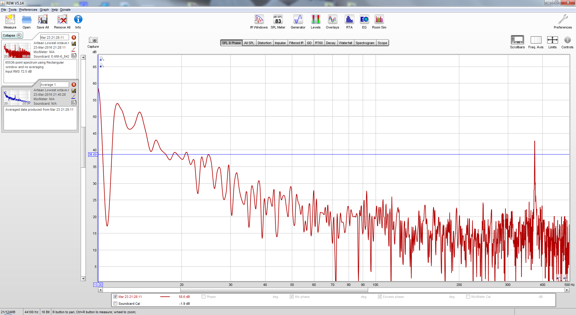
Then compare it to any number of pictures of white noise like this one.

OP's measurement may be partly or completely noise but it isn't white noise. The only way it could possibly be white noise is if it was noise with filters applied which is exceedingly unlikely.
I'll look into the Beringher software and see if I can make up a preset for Ron.
You don't need the Behringer software, this can probably all be done within Hornresp.
All you need is the Hornresp file for the original design and then use the Filter Wizard to make a high pass filter without using any settings below 20 hz.
Ideally the actual cab tuning should be verified first.
As an old researcher, I'm skeptical about introducing the midi thingy into the stew.You guys might be impressed that our friend is smart enough to make a MIDI program that will automatically play the notes that he addresses.me the very same method.
Does the midi-thingy (whatever that is???) "play" the tone generator or is it just synthesizing some signal that Apple or whoever thinks is an organ-like sound suitable for computer speakers? Big difference.
B.
You don't need the Behringer software, this can probably all be done within Hornresp.
All you need is the Hornresp file for the original design and then use the Filter Wizard to make a high pass filter without using any settings below 20 hz.
Ideally the actual cab tuning should be verified first.
To make a preset I certainly do need the software.
But you are totally right that we can simulate this in Hornresp.
In fact it could be setup as a fail safe type of a setting that will protect the driver under any or all use.
Might be able to get away with Ron not having to break out a measurement on the box.
I expect that would be a real pain in the butt task.
Not much room in the organ case for this type of stuff.
Guessing that speaker testing could be done from the end of the wire next to the amplifier.
As an old researcher, I'm skeptical about introducing the midi thingy into the stew.
Does the midi-thingy (whatever that is???) "play" the tone generator or is it just synthesizing some signal that Apple or whoever thinks is an organ-like sound suitable for computer speakers? Big difference.
B.
How it works.
MIDI Musical Instrument Digital Interface.
The Artisan box has samples of individual notes that are recorded on a Skinner Organ. As in a real pipe Organ. The sample sets are of the pipes in each individual rank and are playable or better said addressable through the MIDI interface that is setup in the organ console.
The MIDI interface is used to tell the Artisan module what keys are being pressed to play the appropriate sample set.
What Ron posted, was a sample of the electrical signal coming from the Artisan to his computer's line input jack. Not an acoustical measurement. An electrical signal measurement.
It was a 32 foot pitch low C.
And as it is a sample of an actual organ it includes the blower noise. All the samples would depending on where the microphone location was to make the sample recording.
A "dry" sample is usually very close to the pipe mouth and a "wet" sample is done to include some of the natural reverberation of the existing environment.
To make a preset I certainly do need the software.
This is a picture of the Inuke DSP software, top screen is where the high pass data is entered, bottom screen is where the peq boost is entered.
Seriously, this is so easy a trained monkey could enter the inputs.
All he needs is the filter details to enter. Should take approximately 2 minutes to find the filter details once the original Hornresp design record is loaded up in Hornresp.
But still, ideally OP should verify his actual cab tuning first. For BOTH the subwoofers.

- Status
- Not open for further replies.
- Home
- Loudspeakers
- Subwoofers
- Tapped Horn Cabinet for 16 Hz. organ speaker