After building the circuit below, I'm experiencing some low-level hum when the volume is low.
Even with no source connected, I'm still getting hum with the volume set low.
Also, when I connect it to my fiber optics TV receiver, I can hear a high-pitched "whistling" sound when my plasma TV is on. Turn the TV off or disconnect the interconnects and the whistling sound is gone.
Power supply is a LM317/337 adjustable unit like this one:
http://www.ebay.com/itm/260484989112?_trksid=p2060353.m1438.l2649&ssPageName=STRK:MEBIDX:IT
I put everything in a metal enclosure, but the hum and whistle are still there.
I'm wondering if it could be caused by a ground loop.
I used shielded cable(2 24 awg conductors surrounded by a copper braid) from the input RCAs to the volume pot. I connected the outer braid to the RCAs outer body(like normal) and connected the other end of the braid to the ground terminals on the volume pot.
I then ran 2 small twisted wires to from the volume pot to the input of this preamp board.
I've built and used a lot of low-gain op-amp circuits using the same power supply and have never had issues with hum or "whistling" sounds.
Could the higher-gain of this circuit be amplifying the noise and RF trash more to the point that it's a problem?
Any suggestions would be greatly appreciated.🙂
Attachments

After building the circuit below, I'm experiencing some low-level hum when the volume is low.
It's almost certainly a ground loop. Are the input RCAs isolated from the chassis?
Only one end of the shield on the two conductor input cable should be connected.
Does shorting R3 increase or decrease this hum? Have you checked the circuit's
behavior for HF stability with a scope?
Last edited:
Yes, the input and output RCAs are isolated from the enclosure.
I don't understand...If you don't connect the shield at both ends, then how is the ground going to be connected from the RCA's outer cover to the volume pot?
I'm using the small 24 awg wires for left and right + from the RCAs.
Can you point me to a diagram showing what you're referring to?
I don't understand...If you don't connect the shield at both ends, then how is the ground going to be connected from the RCA's outer cover to the volume pot?
I'm using the small 24 awg wires for left and right + from the RCAs.
Can you point me to a diagram showing what you're referring to?
If you don't connect the shield at both ends, then how is the ground going to be connected
from the RCA's outer cover to the volume pot? I'm using the small 24 awg wires for left and
right + from the RCAs.
Ok, I thought you had two separate cables, and were using the two conductors in each as hot and cold.
Then you have the grounds of the input RCAs shorted together, and both connected to the single shield?
If so, change to two separate cables for the L and R channels, and keep the two input grounds separate.
Use each cable's two internal wires as hot and cold for each channel, ground only one end of each shield,
and don't connect the shields to anything else. The shields should not carry current, signal or otherwise.
Or you could use a twisted pair for each input, again keeping the input grounds separate, with no shielding.
This usually works out about as well as using shielded cable in this sort of application.
Last edited:
Then you have the grounds of the input RCAs shorted together, and both connected to the single shield?
That's exactly what I have done. I have the thin, gold-plated ground rings of both RCAs soldered together and the shield carrying the ground signal from them to the volume pot.😱
I'll run twisted pairs from the input RCAs to the volume pot instead of the shielded cable.
I assume I should also separate the ground terminals on the volume pot as well?
Hi ammel68, did you connect the GND (see schematic) to the chassis and/or PE? If you did then there is a signal path SGND to GND through the PE connection.
Can you post some photo's?
Can you test with only one channel powered and connected to a source? And, as Rayma suggested, don't connect the L and R SGND's together.
Can you post some photo's?
Can you test with only one channel powered and connected to a source? And, as Rayma suggested, don't connect the L and R SGND's together.
I'll run twisted pairs from the input RCAs to the volume pot instead of the shielded cable.
I should also separate the ground terminals on the volume pot as well?
That's right. Keep the two channels' input grounds completely separate.
Use an ohmmeter to confirm that the L and R input grounds are now connected together
with a resistance instead of a short. The resistance between the two RCA socket grounds
should be 20 Ohms with no inputs connected, due to the two 10 Ohm resistors between
each input ground and the main ground. The hum should be gone now.
Do you have a scope and function generator? The HF noise "might" be gone now, try it and see.
Otherwise we can troubleshoot that.
Last edited:
I should note that I've built and testing one channel only.
Okay, separating the grounds eliminated any hum with nothing connected. All I hear is some hiss when close to the speaker.
Strange thing...after separating the grounds, I hear sound at a moderate level even with the 10K blue ALPS pot turned all the way down.
Maybe I should try a 50K pot?
As soon as I connect my fiber optic TV receiver, the hum comes back as well as the sound of a 50KW AM radio station in the background. The station is about 2 miles from where I live.
This noise must be entering through the interconnect's center terminal, ground, or both. I don't know.
I don't have a scope or function generator, just some DMMs.
Hi ammel68, did you connect the GND (see schematic) to the chassis and/or PE? If you did then there is a signal path SGND to GND through the PE connection.
Hi Mark,
I haven't connected any grounds to the enclosure, power or signal.
Strange thing...after separating the grounds, I hear sound at a moderate level
even with the 10K blue ALPS pot turned all the way down.
The residual signal level is likely due to the 10 Ohm resistors lifting the pot's ground terminals
above ground by 20xlog(10/10k) = -60dB down, nothing to worry about.
The noise is likely on the input interconnect cable shields, so try connecting a 0.01uF ceramic
(with very short leads) between each RCA input ground terminal (NOT the hot lead) and the chassis.
Last edited:
The noise is likely on the input interconnect cable shields, so try connecting a 0.01uF ceramic
(with very short leads) between each RCA input ground terminal (NOT the hot lead) and the chassis.
Connect one side of the caps to the chassis even though nothing else is connected to it?
I'm not questioning your advice, just trying to understand it.🙂
Connect one side of the caps to the chassis even though nothing else is connected to it?
The two caps go between each RCA ground lug and the chassis close by, with short leads.
They short any HF picked up by the interconnect cables' shields to chassis ground.
The chassis acts as a shield for the circuitry in this case, even if the circuitry is not connected to it.
A nice summary from the horse's mouth: http://www.calex.com/pdf/4ground_shield.pdf
Last edited:
Darn, I don't have any .01uF caps. All I have is .1uF film and SMD ceramic caps.
I suppose that value is too large?
I suppose that value is too large?
Darn, I don't have any .01uF caps. All I have is .1uF film and SMD ceramic caps.
You want ceramic disc types because they have lower inductance.
The 0.01uF value is small, but is still a low impedance to HF noise.
Temporarily you could try whatever you have around, and replace it later on.
Maybe the smt would be the best of what you have if they're 0.1uF or less,
and are film or ceramic types. Extend the leads with small, short solid wires.
Last edited:
I tried a .1uF ceramic cap between the RCA's ground and the chassis. It didn't help with the hum and radio interference.
It did help to make it even quieter when the volume is turned up about half way with no signal. Without the cap, there is some hum and other nasties at that level.
Another thing that helped was connecting the PS's chassis ground to the enclosure. One of the 4 mounting holes has a pad underneath for doing such.
It looks like there's a .1uF cap between the main ground and this pad.
You're right about the noise coming from the interconnect's shields. If I touch just the shield to the RCA's outer jacket, the noise appears even without connecting the center pin.
I got a PM today from the designer. Here's what he stated:
"Preamplifier bandwith is high and that can be reason for your problem. Voltage gain at 1MHz is still 17dB, 0dB is at 17MHz.
One guy from another forum also said to add capacitor 100pF between rca ground and chassis ground(earth). You can add ferrite bead,on rca cable, close to the preamplifier input."
He also suggested changing C3 up to 1000pF, which I did several days ago knowing that was part of the low-pass filter on the input.
I'm no expert in amplifier design, but I feel like the high gain of this circuit is partly to blame for these issues.
A bandwidth of 1MHz also seems ridiculous to me for a audio amplifier.
Any other suggestios, rayma?
I feel like the high gain of this circuit is partly to blame for these issues.
A bandwidth of 1MHz also seems ridiculous to me for a audio amplifier.
An input filter won't help much, if the amplifier itself is unstable.
We can reduce the open loop bandwidth easily enough, if you want to try that.
Increase C6 from 4.7pF to about 270pF. That should make it a dominant pole.
You can tack solder the larger cap (with short leads) across C6 without removing it.
Something like this one should be ok. A npo/cog type is best, 50V-100V.
http://www.digikey.com/product-detail/en/avx-corporation/SR151A271JAR/478-5211-ND/1549697
Last edited:
Thanks rayma. I'll try the capacitor change.
I also question the stability of this amplifier.
The only 2 things I've measured with a meter, bias and DC offset, both fluctuate several mVs and neither are rock steady. Maybe signs of oscillation?
I've never used a DC servo before, so I'm not sure if this is common with them, or not.
I would think the bias shouldn't fluctuate, though.
bias and DC offset, both fluctuate several mVs
Don't worry too much about such small DC offsets or drifting. It could be the input stage
needing better thermal tracking, but it's likely harmless. Or it also could be
the unregulated power supply's fluctuations causing such variation. That said, there's
always a possibility of HF instability in a circuit like this. Is it built on a pcb with a
ground plane? Can you post a link to the original project?
Last edited:
Here's a link to the original project:
http://www.diyaudio.com/forums/analog-line-level/283966-sony-ta-e1-preamplifier-clone.html
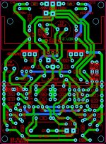
The PCB does not have a ground plane, just what I would call a "star" ground where all the traces come together.
Below is the PCB I'm using minus the DC servo board.
http://www.diyaudio.com/forums/analog-line-level/283966-sony-ta-e1-preamplifier-clone.html
The PCB does not have a ground plane, just what I would call a "star" ground where all the traces come together.
Below is the PCB I'm using minus the DC servo board.
Attachments
minus the DC servo board.
Is there hum problem with the servo inactivated?
Mostly, hum problem is from cabling. Are you sure you don't underestimate cabling?
- Status
- Not open for further replies.
- Home
- Source & Line
- Analog Line Level
- Problem with low-level hum.