I have been trying to find some resource on the web that provides some sort of critical commentary on using unusual crossover values for speakers with rising impedance (as so many do) without a zobel impedance calculation circuit.
I have done this twice now both times 2nd order LR crossovers. Once for real, using measurements taken with HOLM and some trial and error, and once simulated in Speaker Workshop. Both times the results have been excellent on paper/as measured. The built speaker also sounded very good indeed. With both the real and simulated crossover though the speakers needed to be connected in phase. That is, the phase response was not standard.
As an example, Dayton's RS125 P, as simulated, has an good low pass at approx 3.6khz using a .7mH inductor and a 10uF cap. Text book values for the network using the impedance at the same frequency was around .85mH and around 2.1uF.
I prefer this approach because it is simpler to build, dissipates a little less heat and is cheaper to buy. The phase problem is perfectly manageable and reversing the tweeter (or woofer) shows a characteristic crash in the response at crossover. Are there any down sides?
Last edited:
2nd order textbook crossovers might assume a speaker is an 8 ohm resistance, but they're not. Your 8 ohm dayton is probably 6 ohms in series with a voicecoil inductance Le of around 0.6mH.
So in practice, your second order crossover is actually a third order, and so doesn't behave in the predicted way at all. Hence the modelling required.
You'd probably need around 1.8mH and 6.8uF to get any sort of sensible response with even a well-behaved 8 ohm 5" speaker. A metal cone probably needs a cone breakup notch around 8kHz too:
SEAS 5INCH.
I couldn't make any sense at all of your 0.7mH series, 1000uF shunt idea. Or even swapped around. It's mostly a short-circuit, isn't it? It will blow up your amplifier.
Attachments
As I said "Text book values for the network using the impedance at the same frequency." the data puts it at around 10 ohms. Rising impedance from there however makes the crossover next to ineffective using text book values. I have built zobel impedance correction circuits but it seems I can do without them.
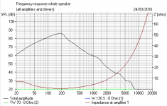
There are no major output irregularities for that driver for the best part of an octave above the crossover point. The cone is paper which helps. The fall off is 12dB, or close enough. Did you have a look at the modeled response?
As I said, I have done something similar before in actual speakers and it worked well (so no amplifier explosions yet at least). I can say though that I am just a hobby builder (so replicate my work at your own risk people 🙂), perhaps a design like this is dangerous in some way - that's part of why I am asking.
I don't see how it could be a short circuit. True the cap is keen to pass frequencies starting lower than normally expected, but with the rising impedance it has to. Don't forget, it is on the speaker side of the inductor. Lower impedance there is, as I understand it, just going to lower the low pass frequency with the existing inductor.
Modeled impedance curves look fine to me, I can measure the speakers I have in operation (though they are stripped down at the moment for painting) where would you expect to see the impedance fall so low and why? This would be the kind of detrimental consequence of the design I would be interested in hearing about.
I was wondering what information there was about this. It strikes me that perhaps zobel impedance correction is most useful when modelling or trial and error is out of the question.
EDIT: Silly me, 10uF not 1000uF, original post modified too. Very sorry Sys7
Last edited:
Silly you indeed. Wasted my time a bit. 😀
IDK if you have the 4 ohm or 8 version of this decent 5" RS125P-8 paper driver either:
Dayton Audio RS125P-8 5" Reference Paper Woofer 8 Ohm - Reference Series - Loudspeaker Drivers By Series - Loudspeaker Components
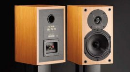
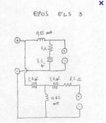
4 ohm is usually easier and gets away with a smaller coil. 1mH and 10uF is near enough usually. The Epos ELS-3 used a polycone, but possibly the simple 4 ohm filter works well enough. I happen to have a couple of these 4 ohm basses, hence my interest.
But Troels Gravesen usually knows what he is doing too. These are 8 ohm (nominal) drivers.
SEAS 5INCH
IDK if you have the 4 ohm or 8 version of this decent 5" RS125P-8 paper driver either:
Dayton Audio RS125P-8 5" Reference Paper Woofer 8 Ohm - Reference Series - Loudspeaker Drivers By Series - Loudspeaker Components
4 ohm is usually easier and gets away with a smaller coil. 1mH and 10uF is near enough usually. The Epos ELS-3 used a polycone, but possibly the simple 4 ohm filter works well enough. I happen to have a couple of these 4 ohm basses, hence my interest.
But Troels Gravesen usually knows what he is doing too. These are 8 ohm (nominal) drivers.
SEAS 5INCH
Attachments
In your simulations, make sure you are including time delay of the tweeter/woofer. You can play around by guessing around 1.2 to 1.4" for most two way systems.
Sometimes the Zobel is useful, sometimes not. I do find it useful sometimes in using the values to nudge the woofer phase crossing one way or another.
BTW, try XSim for pure electro acoustic modelling (no box simulations). It takes FRD and ZMA files. You can grab lots of free FRD and ZMA files from Parts-Express from any Dayton audio driver. It's a great way to play around with this.
Remember that when you simulate, use realistic woofer delays of around 1.2 to 1.4" so you get to suffer some of the crossover issues realistically. 🙂
Best,
Erik
I have been trying to find some resource on the web that provides some sort of critical commentary on using unusual crossover values for speakers with rising impedance (as so many do) without a zobel impedance calculation circuit.
I have done this twice now both times 2nd order LR crossovers. Once for real, using measurements taken with HOLM and some trial and error, and once simulated in Speaker Workshop. Both times the results have been excellent on paper/as measured. The built speaker also sounded very good indeed. With both the real and simulated crossover though the speakers needed to be connected in phase. That is, the phase response was not standard.
As an example, Dayton's RS125 P, as simulated, has an good low pass at approx 3.6khz using a .7mH inductor and a 10uF cap. Text book values for the network using the impedance at the same frequency was around .85mH and around 2.1uF.
I prefer this approach because it is simpler to build, dissipates a little less heat and is cheaper to buy. The phase problem is perfectly manageable and reversing the tweeter (or woofer) shows a characteristic crash in the response at crossover. Are there any down sides?
Whatever works, as long as you don't have dangerous dips in impedance, the response is good, integrates well with the tweeter etc. No "danger" whatsoever. FWIW I've almost never used a purely Zobel + filter arrangement, more often than not it's a series L + RC to ground or L - RC - L or whatever plus notches where required, but very rarely series L + C to ground + Zobel, maybe a couple of times out of 20+ designs and builds.
As for the tweeter being in phase, that's not a "problem". I look at your response and if you say the woofer is 12dB/oct I believe you but the tweeter is obviously flatter (which is not unusual at all in order to make it work when the drivers aren't time-aligned), so it's not suprising that the tweeter is in phase rather than reversed as it would be in a theoretical and even an actual acoustic 2nd order LR, which this clearly isn't.
Cheers,
Cabirio
You may be doing it already but yes, this is absolutely crucial if you hope your sim to have something to do with the real thing.In your simulations, make sure you are including time delay of the tweeter/woofer. You can play around by guessing around 1.2 to 1.4" for most two way systems.
[...]
Remember that when you simulate, use realistic woofer delays of around 1.2 to 1.4" so you get to suffer some of the crossover issues realistically. 🙂
Best,
Erik
Many thanks everyone for all the replies and sorry again Sys7 😱
First up, it seems that the slightly wacky values I end up with when avoiding a zobel are within reasonable limits (as suggested by the modeled impedance plot too). This was my main original question, nice one.
Second offset or 'Z' axis. I had been using a 1/2 inch offset but changed up to 1 inch. Clear differences in the modelled response as expected.
The Dayton speaker is a 5" but is really small for its nominal size, more like a 4.5. I have a Vifa of the same diameter (rated as a 4.5 inch, P11WH-00-08, but with greater Sd than the 5" Dayton) and measured its depth knowing that higher frequencies radiate from nearer the center of the cone. That made me think 1 inch should be about right.
That said the Dayton driver I plan to use has a 'phaze plug', goodness knows what that means for the proper offset, ideas welcome 🙂 Parts express's tech talk website suggests the offset needs to be based on the deepest part of the cone when phase plugs are involved. Don't suppose anyone has one and a ruler? With $200 for postage to Australia I am not going to order the crossover components separately.
Third, some other details. The 5" will enjoy an active 4th order high pass at 400hz. I have made one of Rod Elliott's active crossovers before and it works beautifully. I will be using an 8inch below 400hz. I know that this will outclass the 5" for max SPL but that is OK. The 8" is easy to tune and will have minimal excursion for deep male vocals in some of the blues I dig (can't wait to hear Chris Smither on this setup). Plus it will handle some big bass transients for cinema or break beats.
Fourth, thanks for the software recommendations and comments about using a zobel to fiddle with phase eriksquires. I will check it out xsim.
FWIW I am modeling a Dayton reference tweeter too.
First up, it seems that the slightly wacky values I end up with when avoiding a zobel are within reasonable limits (as suggested by the modeled impedance plot too). This was my main original question, nice one.
Second offset or 'Z' axis. I had been using a 1/2 inch offset but changed up to 1 inch. Clear differences in the modelled response as expected.
The Dayton speaker is a 5" but is really small for its nominal size, more like a 4.5. I have a Vifa of the same diameter (rated as a 4.5 inch, P11WH-00-08, but with greater Sd than the 5" Dayton) and measured its depth knowing that higher frequencies radiate from nearer the center of the cone. That made me think 1 inch should be about right.
That said the Dayton driver I plan to use has a 'phaze plug', goodness knows what that means for the proper offset, ideas welcome 🙂 Parts express's tech talk website suggests the offset needs to be based on the deepest part of the cone when phase plugs are involved. Don't suppose anyone has one and a ruler?
With $200 for postage to Australia I am not going to order the crossover components separately.Third, some other details. The 5" will enjoy an active 4th order high pass at 400hz. I have made one of Rod Elliott's active crossovers before and it works beautifully. I will be using an 8inch below 400hz. I know that this will outclass the 5" for max SPL but that is OK. The 8" is easy to tune and will have minimal excursion for deep male vocals in some of the blues I dig (can't wait to hear Chris Smither on this setup). Plus it will handle some big bass transients for cinema or break beats.
Fourth, thanks for the software recommendations and comments about using a zobel to fiddle with phase eriksquires. I will check it out xsim.
FWIW I am modeling a Dayton reference tweeter too.
- Status
- Not open for further replies.
- Home
- Loudspeakers
- Multi-Way
- Second order crossover - no zobel - trial and error modeling