This talk of bypassing the Buffer on the nc500 ...yes I am aware the Source needs some serious balls to drive it as Bavmike says, but if my Source is on max and it delivers medium volume this test will suffice
It's not just a question of sufficient amplitude, you need a source with a low enough output impedance.
Thanks Theidosis.
Actually i had the DAC turned on (but not playing anything) when i measure.
With the input turned off the readings are in the 50mv range. Is that still worth fixing?
No, 50 mV is OK. It represents 0.0003W into 8 ohm.
Do you have a capacitor between your DAC and amp? I would worry about the DC offset on the DAC output.
It's not just a question of sufficient amplitude, you need a source with a low enough output impedance.
Thanks Julf
It's just for testing really, I don't need it to be loud...would like to hear if anything about the character changes
Is there a jumper on the board or something to bypass?
Could one completely eliminate the XLR jack from the NCore enclosure?
Curious if one could rig up a short (1-2m) interconnect direct to NC400, 2x2 Microfit to XLR plug. It seems that with proper cable strain relief and Pin 1 to ground on both chassis it might be a possibility.
Sure, no reason why not - but also don't really see a reason to do it either. Omitting the XLR connector won't make much of a difference to performance.
OK, I measured the outputs with speakers connected (nominal impedance 6 Ohm) with following results (in mV):
XLR's unplugged: -23(L), -29(R) --> few mV difference vs. no speakers connected.
XLR's connected: -15(L), -36(R) --> (XLR's connected to DAC without signal)
So, looking at the above comments this seems all fine and no further tweaking necessary.
I am still wondering though why DC measured on outputs is in the 170~240mV range when the module input cables (J9) are disconnected and if it can/should be eliminated.
@Stenachio: yes I now see Hypex have revised the SMPS manual last november. It does indeed seem to point in the direction of using J4.1+2 as opposed to J5.3+7 if combined with J6+J7 jumper settings. I also wonder what impact regulated vs. unregulated has both on performance and power consumption from smps and modules. Please share any feedback you receive from them!
No, 50 mV is OK. It represents 0.0003W into 8 ohm.
Do you have a capacitor between your DAC and amp? I would worry about the DC offset on the DAC output.
Thanks Julf.
The current DAC is a MOTU828 MKIII audio interface, while a diy DAC is under development.
I am not sure how the MOTU output is coupled.
I do turn on the DAC before the amps and turn it off after the amps. Even with this I always hear a thump on the drivers as the amps are powered on/off.
Would be great if you could briefly explain the effect of DC offset. Since this is an active setup, does the DC present on the output hold the driver/VC at a non-neutral position (offset seems too low). Or is this more about transiets which can fry them?
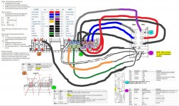
Sorry to bring this particular topic up again - It regarding Bridging NC400.
There is a lot of description (words), but I can't seem to be able to get hold of a "how to" wiring diagram.
Therefore, I base on the descriptive words & come up with some sort of wiring diagram for the more technical guys here to help to confirm my understanding.
Thks.


There is a lot of description (words), but I can't seem to be able to get hold of a "how to" wiring diagram.
Therefore, I base on the descriptive words & come up with some sort of wiring diagram for the more technical guys here to help to confirm my understanding.
Thks.
Last edited:
So, looking at the above comments this seems all fine and no further tweaking necessary.
Indeed. Nicely within spec, no reason to worry.
With infinite source impedance (open circuit) it only takes a minuscule difference in component values/tolerances to generate a significant offset - but it is really not relevant for normal operation.I am still wondering though why DC measured on outputs is in the 170~240mV range when the module input cables (J9) are disconnected and if it can/should be eliminated.
Thanks Julf.
The current DAC is a MOTU828 MKIII audio interface, while a diy DAC is under development.
I am not sure how the MOTU output is coupled.
I do turn on the DAC before the amps and turn it off after the amps. Even with this I always hear a thump on the drivers as the amps are powered on/off.
Would be great if you could briefly explain the effect of DC offset. Since this is an active setup, does the DC present on the output hold the driver/VC at a non-neutral position (offset seems too low). Or is this more about transiets which can fry them?
Julf, any inputs?
thanks
I am not sure how the MOTU output is coupled.
I do turn on the DAC before the amps and turn it off after the amps. Even with this I always hear a thump on the drivers as the amps are powered on/off.
Even if it is capacitor-coupled, you can still get a thump if there is a significant DC offset before the capacitor.
The transients are an issue, of course, but a significant DC offset on the speaker output (remember the ncores are DC-coupled) will cause a driver position bias (and thus more/asymmetric distortion), and also cause extra heat in both the speaker voice coil and the amp.Would be great if you could briefly explain the effect of DC offset. Since this is an active setup, does the DC present on the output hold the driver/VC at a non-neutral position (offset seems too low). Or is this more about transients which can fry them?
Even if it is capacitor-coupled, you can still get a thump if there is a significant DC offset before the capacitor.
The transients are an issue, of course, but a significant DC offset on the speaker output (remember the ncores are DC-coupled) will cause a driver position bias (and thus more/asymmetric distortion), and also cause extra heat in both the speaker voice coil and the amp.
Thanks for clarifying. I will check on the DAC under development to see how it handles this aspect.
@josjev -- Hypex support replied back stating that their original (SMPS1200A400 to NC400) diagram is correct. I've wired mine the opposite way (NC400 to J4 instead of J5) and can confirm it works as well.
I've wired mine the opposite way (NC400 to J4 instead of J5) and can confirm it works as well.
As far as I understand (don't have a SMPS1200 handy to verify) J4.1/4.2 and J5.3/5.7 are connected to the same aux feed, so it doesn't matter which one you use - it only matters from a connector/cable loom point of view.
@Stenachio: yes I now see Hypex have revised the SMPS manual last november. It does indeed seem to point in the direction of using J4.1+2 as opposed to J5.3+7 if combined with J6+J7 jumper settings. I also wonder what impact regulated vs. unregulated has both on performance and power consumption from smps and modules. Please share any feedback you receive from them!
Hypex support replied back stating that their original (SMPS1200A400 to NC400) wiring diagram is correct.
I just finished wiring mine the opposite way and confirm it works as well.
@Julf - Apologies for the double-post. Forgot to mention the "official" reply from Hypex support.
Ok thanks. Did they not mention anything about the J6+7 setting? Are you now running yours set to unregulated? If so, did you notice a difference?
They didn't mention the jumpers and appeared to write it off the proposed (J4 vs J5) alternative as "6 of 1, 1/2 dozen of another". Their reply was rather terse:
"The diagram is correct. The voltage on J5 is always unregulated, regardless of the position of the jumpers."
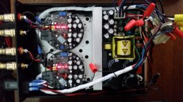
After closely reviewing the manuals I made several changes to the ground locations and elected to use J4 exclusively for the NC400 instead of a combination of J4 and J5.
It sounds great and appears to run much cooler, more like the expected +5W dissipation. Hopefully I'm not a simply a victim of expectation bias and some of the more seasoned members can confirm/deny any factual basis.
Please be advised that there's still a great deal I don't yet understand about electronics. The alterations to the Hypex recommended wiring approach were largely based off careful observation and deductive reasoning, so hopefully there aren't any glaring errors. Comments/criticism on the changes are most welcome.
Here's a summary of the changes. (also listed on the attached image for easier reading)
=-=-
SMPS - J4 Benefits (compared to J5)
+HV
4-6
nFATAL & +Vsig
7-9
HV
10-12
Vdr & -Vsig
The remaining, non HV grounds are J7.4 and J7.10.
Reasoning for chosen ground location:
J7.10 > J1.6
Changed orientation of SMPS, heatsink now in center of enclosure. NC400 modules now face a thick aluminum plate as opposed to copper inductance coils. Increased case ventilation and added taller feet to enclosure.
=-=-
"The diagram is correct. The voltage on J5 is always unregulated, regardless of the position of the jumpers."
After closely reviewing the manuals I made several changes to the ground locations and elected to use J4 exclusively for the NC400 instead of a combination of J4 and J5.
It sounds great and appears to run much cooler, more like the expected +5W dissipation. Hopefully I'm not a simply a victim of expectation bias and some of the more seasoned members can confirm/deny any factual basis.
Please be advised that there's still a great deal I don't yet understand about electronics. The alterations to the Hypex recommended wiring approach were largely based off careful observation and deductive reasoning, so hopefully there aren't any glaring errors. Comments/criticism on the changes are most welcome.
Here's a summary of the changes. (also listed on the attached image for easier reading)
=-=-
SMPS - J4 Benefits (compared to J5)
- Designated NCore supply
- Improved connector type and location
- NC400 connects to J4 only, instead of both
- Unconfirmed, but seems to run cooler
- Appears there are 4 grounding groups revolving around pins 3,4,9 and 12.
+HV
4-6
nFATAL & +Vsig
7-9
HV
10-12
Vdr & -Vsig
The remaining, non HV grounds are J7.4 and J7.10.
Reasoning for chosen ground location:
J7.10 > J1.6
- +/- Vsig now have single ground to J4
- Neighboring pin (Vdr) relative to HV
- Single grounding point for J4
- Applies to +/- Vsig, nFAT and nAMP
- J4.3 closest ground to +/- Vsig, compared to J4.9
Changed orientation of SMPS, heatsink now in center of enclosure. NC400 modules now face a thick aluminum plate as opposed to copper inductance coils. Increased case ventilation and added taller feet to enclosure.
=-=-
Attachments
No taker ?? 😕
Any technical guru/expert able to advise if my understanding below is correct or wrong.
Any technical guru/expert able to advise if my understanding below is correct or wrong.
Sorry to bring this particular topic up again - It regarding Bridging NC400.
There is a lot of description (words), but I can't seem to be able to get hold of a "how to" wiring diagram.
Therefore, I base on the descriptive words & come up with some sort of wiring diagram for the more technical guys here to help to confirm my understanding.
Thks.
An externally hosted image should be here but it was not working when we last tested it.
An externally hosted image should be here but it was not working when we last tested it.
An externally hosted image should be here but it was not working when we last tested it.
No taker ?? 😕
Any technical guru/expert able to advise if my understanding below is correct or wrong.
Looks OK to me - just be aware that it will halve the speaker impedance the amps "see", so not suitable for very low-impedance speakers.
- Status
- Not open for further replies.
- Home
- Amplifiers
- Class D
- Hypex Ncore