ok I didnt realize 25 was that high. so that's out. but what about the 20 Vrms version? AS-4220
so you're saying getting 500VA 18Vrms would be a better fit that let's say 400VA 20 Vrem shielded?
Each transformer is rated for a certain amount of volts (V) at a certain number of amps (A), hence the product VA you see. Once you fix a voltage, the VA rating will tell you how much AC current is available for use. You are comparing two rather different transformers there.
You need to keep in mind the rectified DC voltage you'd get from the transformers. The 18VAC transformers give roughly 23-24VDC after rectification (18VAC*1.414=25.5VDC, but we lose some across the rectifier diodes and RC filter in the power supply), which is what the Firstwatt amps are designed to use. On the other hand, 20VAC will give you around 26VDC rails. This will likely be fine for the input JFETs, but I wouldn't push it personally since the 2SJ74 datasheet claims it is a 25V part (even though users have reported it will sustain more). Your earlier question about the 25VAC transformer would give rails at 32V or so and would likely fry the JFETs instantly.
For a first build, it is probably best to just stick with the stock choices so that you maximize the likelihood of success. So, shoot for the 400VA, 18VAC transformer that most of us use.
Have you perused 6L6's F6 build guide? If not, search the forums for it. He walks through many part selections and has pictures of assembly.
Last edited:
thanks. yes i am going through the whole thread. the reason Im asking these is that the shielded 400VA 18 Vrms is out of stock. im not deviating from the design on purpose.
I might add that it is very very confusing that multiple times in the thread various modifications to the original design come up by 6L6 and others. the first one is in post #3 that basically says instead on the 5.1 volt diode in the schematic, use the 9.1 volt one. ofcourse others already explained that one to me. im just making a point that im not purposefully making this more complicated.
i greatly appreciate you guys help and direction.
No, the voltage (25 is too high). It will cook your jfets. You need an 18 Volt transformer which gives around 23 Volts DC after rectification and filtering.
The 400 VA 18 Volt is out of stock. I used this one ---
AN-5218 - 500VA 18V TRANSFORMER---for my build and it worked perfect and its in stock. It is not shielded but that didn't cause me any problems. It is $55 compared to $51
for the 400 VA, only $4 more.
+1 for AN-5218
I have been using independent PSUs for each channel and two of this transformer stacked:
AS-2218 - 200VA 18V Transformer - AnTek Products Corp
AS-2218 - 200VA 18V Transformer - AnTek Products Corp
it's OOS
gotcha
ok I didnt realize 25 was that high. so that's out. but what about the 20 Vrms version? AS-4220
so you're saying getting 500VA 18Vrms would be a better fit that let's say 400VA 20 Vrem shielded?
How about this: AN-5218 - 500VA 18V Transformer - AnTek Products Corp
Russellc
thanks. yes i am going through the whole thread. the reason Im asking these is that the shielded 400VA 18 Vrms is out of stock. im not deviating from the design on purpose.
Surely it's not more than a month to restock the transformer.
wow the cases are so expensive .... what is the smallest size chassis that may be used to house an F6 with 400VA or 500VA trans? 4u and 5u are quite pricey!
4U 300mm
Buy the deluxe 4U - it is worth every penny, and will greatly assist in making your build easier, less error prone, and successful.
Sometimes it just makes sense to buy the good one first.
Also, if you are going to buy an Antek, I cannot strongly enough recommend getting an AS- series (shielded) because I've never had one hum, and honestly, just get the 300VA. If Papa uses 300VA in the factory FW builds, that's good enough for me. (I used a 400 in the build guide because I had it on hand, if I needed to order one, I'd have gotten an AS-3218 or AS-3220)
Last edited:
4U 300mm........
besides several 6L6's build tutorials (must see for any greenhorn), you can take a look at recent 4U/400mm build
not much words , but pictures are universal as always
Judging where you are, and where you want to end up, let me make a few suggestions:
1. Get a GOOD soldering iron (even better, a good soldering workstation).....and practice, practice, practice your soldering technique on scrap printed circuit boards (salvage them from some old radios, CD players, etc). Read: no sense practicing on your good boards.....once you screw 'em up, the tend to remain screwed up(!)
2. When you get to building.....build the power supply first.....and only the power supply and AC line (transformer primary). Test the power supply output, using the famous light bulb tester on the AC side. If your voltages read a little high, that's fine--remember that you probably only have a few bleeder resistors for your loads. After you power down the power supply, give the power supply electrolytic caps time to discharge(!).
3. Then build ONE channel of the amp. That will tell you if you have the schematic and your wiring correct. If it works, fine..... if not, you have the "spare parts" from the second (uninstalled) channel to help get the first channel working. As a plus, if you get the first channel working, you can take voltage measurements to help you after you wire the second channel (if you have to troubleshoot the second channel).
4. To many folks seems to DIY the whole amp as one unit--and then wonder why the let the smoke out from both channels (and/or the power supply). Take your time, and work thru the schematics is small bites (power supply, one channel, second channel).
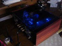
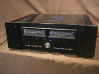
You have friends here. Despite your newbie disabilities as a physics major, we can help get you through....... and Oh.....I graduated with one of those physics degrees, too! (Pics of my "first effort"...a Pass DIY F-5 are attached)
The Pass designs are superb, provide outstanding results, and are perfect for a new builder. Welcome on board.
P.S. DO NOT overlook polarities on your bridge rectifiers, electrolytic capacitors and (of course) your semiconductors!!!
1. Get a GOOD soldering iron (even better, a good soldering workstation).....and practice, practice, practice your soldering technique on scrap printed circuit boards (salvage them from some old radios, CD players, etc). Read: no sense practicing on your good boards.....once you screw 'em up, the tend to remain screwed up(!)
2. When you get to building.....build the power supply first.....and only the power supply and AC line (transformer primary). Test the power supply output, using the famous light bulb tester on the AC side. If your voltages read a little high, that's fine--remember that you probably only have a few bleeder resistors for your loads. After you power down the power supply, give the power supply electrolytic caps time to discharge(!).
3. Then build ONE channel of the amp. That will tell you if you have the schematic and your wiring correct. If it works, fine..... if not, you have the "spare parts" from the second (uninstalled) channel to help get the first channel working. As a plus, if you get the first channel working, you can take voltage measurements to help you after you wire the second channel (if you have to troubleshoot the second channel).
4. To many folks seems to DIY the whole amp as one unit--and then wonder why the let the smoke out from both channels (and/or the power supply). Take your time, and work thru the schematics is small bites (power supply, one channel, second channel).
You have friends here. Despite your newbie disabilities as a physics major, we can help get you through....... and Oh.....I graduated with one of those physics degrees, too! (Pics of my "first effort"...a Pass DIY F-5 are attached)
The Pass designs are superb, provide outstanding results, and are perfect for a new builder. Welcome on board.
P.S. DO NOT overlook polarities on your bridge rectifiers, electrolytic capacitors and (of course) your semiconductors!!!
Attachments
Last edited:
Wella does hairspray, Weller do the irons
Nothing wrong with having your hair look nice while you are building an amp.😛
But it's much cheaper! 😀Wella does hairspray, Weller do the irons
You really got here good advices, the best is: Ask if you have a question!
I can remember the day when I started to decide, collect and then build an amplifier, it was so overwhelming! Enjoy it!
Here is somewhere a thread with advises to newbies: What you never should do, but some people did. My favourite: Ever be sure to grab the soldering iron in the correct side!
And you should measure all resistors before you solder them in. Normally they are all correct, but if not, you'll look for the bug this causes many hours/days/...
Read the datasheets and try to understand what all the numbers mean. Compare them e.g. when you decide which capacitor you choose for the F6.
Use the types of componets others here with a big mileage choose! Look then into the datasheet and compare, find out why.
Bigger is better in am power supply is really tempting, but you get higher charging ripples. I would do what Nelson does, ok, here just 100AV more, so a 400VA 18V is perfect. With shielding, and dual 18V outs. If you can, also with 2x115V in, you never know if you'll live one day in a country with 230V for a period of time. But now I'm overdoing. 😉
There's another F6 building thread, and there's a super advice from Buzz: Instead of buying a Zener, buy a LM329dz. It has less noise.
The thread's link is http://www.diyaudio.com/forums/pass-labs/284774-f6-amp-semisouth-sjep120r100.html
If you don't have a mulimeter, buy one good enough and borrow you additional for powering of the amp. Or buy 2 cheap more. As you live in the US, this is all very cheap for you compared to other countries.
Brymen is an OEM manufacturer, you get good quality (really tested for safety, not like most of the asien stuff), as it won't explode in you hand if you measure something with higher voltages/amps and set-up the bloddy thing falsely. (you get a lot of information for this in the internet).
Others of cause make also nice stuff.
So, I'll stop here!
Have fun
Matthias
Judging where you are, and where you want to end up, let me make a few suggestions:
1. Get a GOOD soldering iron (even better, a good soldering workstation).....and practice, practice, practice your soldering technique on scrap printed circuit boards (salvage them from some old radios, CD players, etc). Read: no sense practicing on your good boards.....once you screw 'em up, the tend to remain screwed up(!)
2. When you get to building.....build the power supply first.....and only the power supply and AC line (transformer primary). Test the power supply output, using the famous light bulb tester on the AC side. If your voltages read a little high, that's fine--remember that you probably only have a few bleeder resistors for your loads. After you power down the power supply, give the power supply electrolytic caps time to discharge(!).
3. Then build ONE channel of the amp. That will tell you if you have the schematic and your wiring correct. If it works, fine..... if not, you have the "spare parts" from the second (uninstalled) channel to help get the first channel working. As a plus, if you get the first channel working, you can take voltage measurements to help you after you wire the second channel (if you have to troubleshoot the second channel).
4. To many folks seems to DIY the whole amp as one unit--and then wonder why the let the smoke out from both channels (and/or the power supply). Take your time, and work thru the schematics is small bites (power supply, one channel, second channel).
You have friends here. Despite your newbie disabilities as a physics major, we can help get you through....... and Oh.....I graduated with one of those physics degrees, too! (Pics of my "first effort"...a Pass DIY F-5 are attached)
The Pass designs are superb, provide outstanding results, and are perfect for a new builder. Welcome on board.
P.S. DO NOT overlook polarities on your bridge rectifiers, electrolytic capacitors and (of course) your semiconductors!!!
got a weller soldering station but I definitely do need to practice my soldering since last time i used it i did mess up a lot.
I really appreciate all the tips and advice
But it's much cheaper! 😀
You really got here good advices, the best is: Ask if you have a question!
I can remember the day when I started to decide, collect and then build an amplifier, it was so overwhelming! Enjoy it!
Here is somewhere a thread with advises to newbies: What you never should do, but some people did. My favourite: Ever be sure to grab the soldering iron in the correct side!
And you should measure all resistors before you solder them in. Normally they are all correct, but if not, you'll look for the bug this causes many hours/days/...
Read the datasheets and try to understand what all the numbers mean. Compare them e.g. when you decide which capacitor you choose for the F6.
Use the types of componets others here with a big mileage choose! Look then into the datasheet and compare, find out why.
Bigger is better in am power supply is really tempting, but you get higher charging ripples. I would do what Nelson does, ok, here just 100AV more, so a 400VA 18V is perfect. With shielding, and dual 18V outs. If you can, also with 2x115V in, you never know if you'll live one day in a country with 230V for a period of time. But now I'm overdoing. 😉
There's another F6 building thread, and there's a super advice from Buzz: Instead of buying a Zener, buy a LM329dz. It has less noise.
The thread's link is http://www.diyaudio.com/forums/pass-labs/284774-f6-amp-semisouth-sjep120r100.html
If you don't have a mulimeter, buy one good enough and borrow you additional for powering of the amp. Or buy 2 cheap more. As you live in the US, this is all very cheap for you compared to other countries.
Brymen is an OEM manufacturer, you get good quality (really tested for safety, not like most of the asien stuff), as it won't explode in you hand if you measure something with higher voltages/amps and set-up the bloddy thing falsely. (you get a lot of information for this in the internet).
Others of cause make also nice stuff.
So, I'll stop here!
Have fun
Matthias
thanks Matthias, this would be it, right?
LM329DZ/NOPB Texas Instruments | Mouser
got a weller soldering station but I definitely do need to practice my soldering since last time i used it i did mess up a lot.
I really appreciate all the tips and advice
Practice putting the tip so that it touches both the wire lead and the pad at the same time. Hopefully your solder station is the type that keeps the tip at a constant temp. When you touch the component lead, it tends to cool the tip. With the type of Iron that keeps heat constant, it will immediately up the jice, causing temps to be constant. This is a big help.
While the tip is touching both lead and pad, heat until solder melts on the pad. It should flow neatly covering the pad, then finish by coming up the lead with the tip. This should result in a nice shiney upside down cone solder joint. If it doesnt cover the pad with an even flow, and is only balled up on the lead above the pad, and not shiney, it is likely to end up a cold solder joint....the cause of much frustration, the failure is typically intermittant.
Russellc
Yes, it's that in the link, if you buy from Mouser.
And, as Russellc mentions, soldering is important, and done right an art.
I liked the tutorial very much you can find under this link: http://www.diyaudio.com/forums/construction-tips/209333-awesome-soldering-lessons-youtube.html
It's the best I've seen.
And, as Russellc mentions, soldering is important, and done right an art.
I liked the tutorial very much you can find under this link: http://www.diyaudio.com/forums/construction-tips/209333-awesome-soldering-lessons-youtube.html
It's the best I've seen.
(Pics of my "first effort"...a Pass DIY F-5 are attached)
You bring the beauty into the beast. What a work!
- Status
- Not open for further replies.
- Home
- Amplifiers
- Pass Labs
- The F6 build of the century :) (I want to learn everything)