Cool!
Are you sure the foam isn't conductive (many are for ESD reasons)?
Samuel
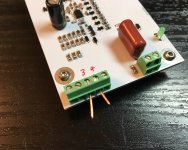
The output is hyper sensitive to the environment. Just pressing the foam can make a massive difference (usually settling the output lower).
Are you sure the foam isn't conductive (many are for ESD reasons)?
Samuel
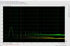
The trace with the 1k resistor should be much higher. Looks like something basic is wrong--check DC operating points, gain, frequency response etc.
Samuel
Samuel
* All JFETs are forced to operate at the same Vgs (as source and gate are shorted together). They will only operate at equal drain current, and thus very similar transconductance, if their "standalone" Vgs at the desired fractional drain current is matched.
Pin 3/4 of J102 go to pin 2/3 of the output XLR.
Samuel
Samuel have you tried a Monte Carlo simulation? The noise for a typical 2 or even 3X Idss range has a very small variance with no matching. Mr. O. Papa built a phono front end with masses of unmatched BF862's. By the time you get to the fourth root of Id the variation is pretty small.
Last edited:
Samuel have you tried a Monte Carlo simulation? The noise for a typical 2 or even 3X Idss range has a very small variance with no matching. Mr. O. Papa built a phono front end with masses of unmatched BF862's. By the time you get to the fourth root of Id the variation is pretty small.
I don't recall the details--the design phase is years back. I agree that the voltage noise as function of mismatch is pretty benign. On the other hand, sensitivity to secondary noise sources should be a second rooth function (directly related to gm), so a bit more critical.
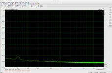
I ran the measurements again. 1k resistor in green. Shorted input brown.
Looking good!
Samuel
I ran the measurements again. 1k resistor in green. Shorted input brown.
Congratulations on a successful build.
Could you tell me how you managed to measure down to -180dB. Thanks.
Could you tell me how you managed to measure down to -180 dB.
The scaling is (essentially) arbitrary in this plot--the ratio (difference in dB) between the two measurements matters. If the FFT size is made larger, the bins get narrower and the noise drops (less noise energy per bin). Arbitrarily low noise floors are possible that way. If you want to measure noise with an FFT, you need special scaling to compensate for this--unfortunately many software packages don't support this. A commonly misunderstud topic.
Samuel

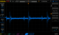
I only now had time to connect my signal generator. I dialled in 10mVpp. I connected my scope to the output of the pre amp and selected it to measure Vpp. Divisions: 2ms and 5V. From 50Hz all the way through to about 130kHz or so it displayed Vpp of 10.6-8V (it flickered between the two). Above about 130kHz occasionally 10.4Vpp would be displayed, more often as I increased frequency. At 10Hz (1s per division) Vpp was a constant 10.6V.
Samuel, can you please expand on your last comment? So there's no remotely reliable vertical scale? How would one determine, for example, the line rejection of a measured power supply if there's no reference for noise floor?
PS: I did indeed change the foam I was using
Samuel, can you please expand on your last comment? So there's no remotely reliable vertical scale? How would one determine, for example, the line rejection of a measured power supply if there's no reference for noise floor?
PS: I did indeed change the foam I was using
Last edited:
100 kHz at such high output levels will probably drive the amplifier into slew-rate limiting. If the purpose is to measure frequency response, I'd reduce the input level to about 1 mV (peak, peak-peak or RMS).I only now had time to connect my signal generator.
The considerations apply to random signals only. Residual ripple in a voltage regualtor is a steady-state signal, related to the mains frequency; it is measured correctly with standard FFT settings. If unsure what you're looking at, you can double (half) the FFT size. Random noise will drop (rise) by 3 dB. The level of a steady-state signal won't change.Samuel, can you please expand on your last comment? So there's no remotely reliable vertical scale? How would one determine, for example, the line rejection of a measured power supply if there's no reference for noise floor?
Recommended reading: The Fundamentals of FFT-Based Signal Analysis and Measurement in LabVIEW and LabWindows/CVI. The topic of noise scaling is adressed in section 4, but it's probably wise to go through the entire text.
Samuel
Thanks. Yes, the intention was to just do a quick check of the build with respect to gain and frequency response. I just kept dialling higher frequency until I saw a drop in output. It seems 4mVpp is the lowest my new signal generator will go. (I thought its specs went down to 2mV but it seems not...)
Thanks. I will definitely read the linked text.
Thanks. I will definitely read the linked text.
I built a version of Self's low noise balanced to single-ended input. I'd like to measure the noise performance of this board but I am somewhat confused as to exactly how to do so. Clearly I need to power it up and apply a signal to the input, and measure the output. I have available to me an ESI Juli@ sound card with balanced inputs, ARTA, a signal generator and this amplifier. Any guidance appreciated.
Last edited:
I built a version of Self's low noise balanced to single-ended input. I'd like to measure the noise performance of this board but I am somewhat confused as to exactly how to do so. Clearly I need to power it up and apply a signal to the input, and measure the output. I have available to me an ESI Juli@ sound card with balanced inputs, ARTA, a signal generator and this amplifier. Any guidance appreciated.
If you want to measure noise you don't need an input signal. Generally you terminate the input with a resistance that mimics the expected source resistance, then measure output noise, divide by gain and that gives you input-referred noise.
Or short the input is you want the noise of the amp itself only.
Jan
Ok that makes sense. When you say terminate the input do you simply mean a resistor to ground (i.e. across the inputs)? (E.g. 50R)
For SNR I'd need an input signal, no? I've never found a good source for guidance on how to conduct the plethora of tests one might need/want in diyAudio. Any references appreciated.
Looks like I've managed to damage my Juli@ XTe and I just found out when I went to purchase another that they're not making them anymore. I'm fuming. My Mac Pro can only take PCIe and that card was really very effective. (Cards like the Asus Sonar STX don't work in a Mac.) I also use the digital section of the XTe in my audio server. Hopefully that doesn't stop working...
Ok that makes sense. When you say terminate the input do you simply mean a resistor to ground (i.e. across the inputs)? (E.g. 50R)
For SNR I'd need an input signal, no? I've never found a good source for guidance on how to conduct the plethora of tests one might need/want in diyAudio. Any references appreciated.
Looks like I've managed to damage my Juli@ XTe and I just found out when I went to purchase another that they're not making them anymore. I'm fuming. My Mac Pro can only take PCIe and that card was really very effective. (Cards like the Asus Sonar STX don't work in a Mac.) I also use the digital section of the XTe in my audio server. Hopefully that doesn't stop working...
Yes terminate the input.
For S/N you can measure noise with shorted input, say you measure 10uV at the output. Then if you have a hypothetical output signal of 1V, that is 1/100000th of noise, so S/N ratio for that 1V would be -100dB.
If your amp gain is 100, your input-referred noise is 100nV. That 1V output signal would need 10mV input and with the 100nV is the same S/N of -100dB.
Don't think too much - it's quite intuitive 😉
Jan
Ok I think I have it. Thanks. I've yet to become intuitive thinking with dB (and scientific notation for that matter).
If anyone has a source for SMD NJM4580 please do let me know as I can't find them anywhere...
If anyone has a source for SMD NJM4580 please do let me know as I can't find them anywhere...
Ok I think I have it. Thanks. I've yet to become intuitive thinking with dB (and scientific notation for that matter).
If anyone has a source for SMD NJM4580 please do let me know as I can't find them anywhere...
In voltage, every factor of 10 is 20dB. Factor of 100,000? Five zeroes = 5 times 20dB = 100dB of course 😉
Depending on whether it is 10x (+20dB) or 1/10th (-10dB).
So, 1000x is +60dB, 1/1000 is -60dB.
Jan
Thx
Another noise question if I may. My sound card needs a new op amp. The OAs en situe are NJM4580C judging from the markings. I can't find these but the NJM4580 seem to be available. Link to New Japan Radio website.
These look to be the same in every way except supply (non C version has wider supply range), ft and noise. With respect to the latter, the non-C has noise described as "0.8μVrms typ." while the C version has "5nV/√Hz typ. at f=1kHz". Is there a way to compare these?
- Home
- Design & Build
- Equipment & Tools
- Groner's Low noise measurement amp from Linear Audio vol 3 - spare boards?