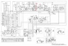
Thank you Mooly,C33 is the "lower" arm of the feedback return network. The tone controls are wrapped around the feedback network of the discrete driver stage.
In another forum I've heard someone saying to double their capacitance value (to 470uF) as they "feed" the preamp section... I kept original 220uF value anyway.
An externally hosted image should be here but it was not working when we last tested it.
ivanlukic said:Karl,
Thanks for the schematic.
You are welcome! Thank you for the thread! 🙂
Doubling it would make little difference. The -3db lower cut-off point of the 220uf is down at 2Hz anyway. 220uf is fine.
pma-737 recap
Hi everybody,
this thread, forum and some of its members (thanks Karl) were great source of information about Denon PMA-737 for me and I want to share some useful information collected in process of my unit restoration. My english is self taught, so consider yourself warned if you are easily upset with rather "innovative" grammar constructs.
I have purchased the unit in good working order and was impressed with the sound. Wanted to make it even better and have some DIY fun.
Restoration/tweaking stages:
- transformer screws tightening
- relay change
- opamps sockets installation and testing of different opamps
- inputs board caps
- main board caps (multiple sessions)
- main filter caps
Transformer
-----------
There is a slight transformer buzz or hum. Nothing dramatic, it is hearable only via headphones and when you put ear couple of centimeters from transformer unit.
I have tightened all the bolts (on transformer unit and on chassis), but it did not helped. There are 3 possible reasons so far I researched. The unit is running slightly above to original parameters (220V vs 230-240V ' ). DC pollution in mains. Or the buzz is result/feature of the age and construction of the transformer itself.
I have recently build also a mains DC filter from a kit and the buzz did not changed.
Relay
------
- Omron G4W-2212P-US-TV5 24VDC is perfect fit original Matsushita relay (can handle bigger current, coil has slightly bigger resistance, body is approx. 0.5 mm wider, and legs are little bit longer = easy fix)
- Impact - slightly better click than old one, noise floor stayed the same, no other changes positive or negative effects noticed.
Opamp Phono
-----------
- mitsubishi M5218P replaced with TI LM4562NA in socket
- phono input noise without change, i like the sound but improvement is rather subtle
- did not noticed any oscilation
- replaced with OPA2134PA, change very subtle if any, sounded somehow more pleasurable so it stays (confirmation bias?)
Opamps main board
-----------------
- only one half of dual chip is used
- LM4562 instead of M5218P was oscillating badly (distortion)
- NE5532P works OK, voltages across main board are little bit lower approx. 13V instead of 14V on D9 and D11 diodes
- NE5532P replaced with OPA2134PA, more quiet (need to turn the volume little bit more) => nasty side effect biasing circuit stopped working and voltages across main board were lower, 5.5V instead of 14.5V on D9 and D11 diodes, amplifier played but little bit different but probably not because of opamp characteristic but because lack of quiescent current (measured via fuse clamps)
- i have returned back the original mitsubishi opamps, finding replacement opamp for this positions is not trivial 🙂
Input board
-----------
- two ceramics (14 nF) caps found instead of electrolytics (1 pF 50V) -> replaced with parts according to service manual and board markings
- two jumpers instead of electrolytics - replaced with electrolytic capacitors according to service manual (so far i checked the pictures of different units, EU versions used to have the 2 x ceramic capacitor + 2 x jumper combo installed instead of capacitors)
- it seems according to pictures of different units that US version used to have 4 electrolytic capacitors on the positions that differ in my case and EU version had 2 x ceramic and 2 x jumper
- most of to caps were OK according to the tester, some of them were on the tolerance edge with higher ESR
- phono input sound seems to be more "true" after the recap
- trim pots were replaced with vishay multiturn and phono balance was readjusted
Main board:
-----------
- replaced on turn trim pots with multiturn vishay, setting of idling current is much comfortable and more precise now, one leg needs to be prolonged
Capacitors replacement (iterations):
------------------------------------
All capacitors except 1uF 100V (Panasonic FC) and main filter caps were Elna Silmic II. I wanted to buy them at once from one EU supplier which more or less decided what brand/type it will be.
- C7, C8 replaced with increased value 4.7uF instead of 1uF (recommended by Karl), C13, C15 with values according to service manual -> sound improvement probably very subtle, sounded nice before sounds nice after, it should extend headroom especially in low end frequencies, bass drum in my testing recording sound little bit different (confirmation bias?)
- C21 - C34 (only electrolytics) - no change in noise, no change in sound, on C21 1uF 100V position was 1uf 50V instead
- C35 - C82 (only electrolytics) - no change in noise, no change in sound, 47uF 50V elnas are on some positions tight fit, doable, but not pretty
- C202 - 214 - main filter caps are 3 pin with non standard pin spacing 14 mm, nichicon KS with standard 10 mm snap in pins was used. The pins were bent and the body of capacitor was partially glued with neutral silicone
Conclusion:
-----------
Primary motivation for recap was higher noise floor and slight transformer hum (nothing dramatic, little bit annoying on headphones) these were not fixed or significantly lowered by recap. All the electrolytics were good according to my tester (chinese MK-328). Some of the little ones were on the tolerance edge but in general the electrolytics in my unit were in great shape considering the age.
The caps will probably need some time to burn in. The sound of the unit changed in a positive way, especially the phono preamp.
The unit is easy to work on with easily accessible boards and I learned a lot in the process 🙂.
Pics of non tweaked unit (not mine): Inside Hi-Fi: Denon PMA-737
Pics of my unit in random order: Denon PMA-737 recap - Album on Imgur
That's all folks 🙂.
I see I'm subscribed to this thread 🙂
Quick comment... the D9 and D11 voltages falling when replacing the opamps is to be expected because these diodes are simple shunt regulators fed resistively via those 4k7 1 watt parts. The 4562, 5532 etc are all more current hungry and are pulling the voltage down. All you need do is drop the value of these resistors such that the voltage comes back to the nominal 15 volts and that a small current of say 20 milliamps is flowing in the zeners.
If the voltage across the zeners falls below the marked value then they are starved of current and the supplies to the opamp are no longer regulated and noise free.
I see I'm subscribed to this thread 🙂
Quick comment... the D9 and D11 voltages falling when replacing the opamps is to be expected because these diodes are simple shunt regulators fed resistively via those 4k7 1 watt parts. The 4562, 5532 etc are all more current hungry and are pulling the voltage down. All you need do is drop the value of these resistors such that the voltage comes back to the nominal 15 volts and that a small current of say 20 milliamps is flowing in the zeners.
If the voltage across the zeners falls below the marked value then they are starved of current and the supplies to the opamp are no longer regulated and noise free.
Thanks for suggestion. I am an amateur without formal electrotechnical education, but it makes sense to me.
Putting appropriate trim pots on R81 and R83 position would be maybe even more practical for opamp rolling.
In theory perhaps 🙂 Although the opamp currents are small in the scheme of things, they are beyond what most trim pots could withstand.
Its quite easy to arrive at a suitable value, even by trial and error. With the opamps you wish to try fitted (for example all LM4562) you could then add a parallel 10k across each of the two resistors and observe the 15 volts.
Does it come up to the correct value ? If not then add a second 10k in parallel and so on. When the 15 volts is correct you then calculate the new value required.
There is an even better way. Do the above method, but stop when the voltage is a little short of the correct value, say 12 volts. Now measure the voltage across the 4k7 resistor and from that calculate the current using ohms law. That gives us the current drawn by the opamps alone. The zener isn't working at this point.
You then measure the voltage at the top or 'input' of the 4k7 (lets say it was 35 volts) and you subtract from that the 15 volt zener voltage. So that gives 20 volts that we need to 'lose' across the new resistor.
We know the opamp current (because you calculated it... lets say it was 46ma), and we know the voltage that will be across the resistor (20 volts).
We now add a suitable zener current of say 20ma to the opamp current. So that gives 66ma in total.
20 volts at 66ma requires a resistor of 303 ohms. So we would use say 330 ohm. The wattage needed would be 1.32 watt (W=I*V or 0.066*20). We would use a 2 watt part.
And your English is excellent 🙂
You're very welcome 🙂
And if you do tweak the resistors then please remember that its done as a 'one off' to suit the actual opamp type in use at that time.
I say that because if you take the worked example above and then went and fitted say TL072's that draw only a couple of milliamps then you would find the zener was passing nearly the full 66ma we calculated. 66ma @ 15 volts is 0.99 watt. You could well find the zeners fitted are common smaller 0.4w types. So not good for the zener in that situation.
So you can see it all depends on the actual voltages used in your unit. And if you wanted to have sockets for the IC's and experiment with different ones then calculate a worst case scenario and fit zeners that would be OK with any opamp. That would probably mean fitting 1.3watt 15 volt zeners.
You're very welcome 🙂
And if you do tweak the resistors then please remember that its done as a 'one off' to suit the actual opamp type in use at that time.
I say that because if you take the worked example above and then went and fitted say TL072's that draw only a couple of milliamps then you would find the zener was passing nearly the full 66ma we calculated. 66ma @ 15 volts is 0.99 watt. You could well find the zeners fitted are common smaller 0.4w types. So not good for the zener in that situation.
So you can see it all depends on the actual voltages used in your unit. And if you wanted to have sockets for the IC's and experiment with different ones then calculate a worst case scenario and fit zeners that would be OK with any opamp. That would probably mean fitting 1.3watt 15 volt zeners.
Ok.
Since my drawer stock of suitable testing resistors is non-existent I am asking following question. Can't be the resistor value for particular opamp calculated from values present in schematics and in opamp datasheet?
E.g. for original Mitsubishi M5218P there is value named 'Circuit current' with max 6 mA.
Modern opamps e.g. OPA2134PA have different current related values in datasheet e.g. Short-circuit current 40mA.
Up to a point, yes, you can get a good idea of what's needed.
If you look at the data sheet for an opamp it will give typical and worst case current consumption. This shows the OPA134/2134/4134 data sheet and the current is 5ma worst case 'per amplifier'. The per amplifier means that the dual 2134 will draw 10ma, the quad 4134 would draw 20ma.

So that is the current it draws just sat there doing nothing. When a signal is present that current changes a little as the opamp has to drive the circuitry around it. Typically you are only going to see at most a couple of milliamps change in the current in an amplifier like yours but the 40ma maximum output (or short circuit current you mentioned) is the potential current the opamp could deliver if the designer wanted.
For example, suppose the opamp was used as a headphone amp. You might need the ability to deliver perhaps 20 or 30 milliamps of signal to the headphones. So the supply would need to cope with that.
If you look at the data sheet for an opamp it will give typical and worst case current consumption. This shows the OPA134/2134/4134 data sheet and the current is 5ma worst case 'per amplifier'. The per amplifier means that the dual 2134 will draw 10ma, the quad 4134 would draw 20ma.
So that is the current it draws just sat there doing nothing. When a signal is present that current changes a little as the opamp has to drive the circuitry around it. Typically you are only going to see at most a couple of milliamps change in the current in an amplifier like yours but the 40ma maximum output (or short circuit current you mentioned) is the potential current the opamp could deliver if the designer wanted.
For example, suppose the opamp was used as a headphone amp. You might need the ability to deliver perhaps 20 or 30 milliamps of signal to the headphones. So the supply would need to cope with that.
Hello.I also have this amplifier Denon PMA-737.Looking at the schemating ,resistors R81,R83 (4.7K) that feed the D9,D11 15V zener diodes provide about 6ma.Isnt it a bit low?
Even with original values shown,M5218P draws 3ma total and about 2.92ma are drawn by R85.nothing is lft for the zener to regulate properly.
A member used other opamps there like OPA2134,LM4562,NE5532 and claimed problems appeared like distortion,not being able to control the quiscent current and oscillation.
current demand for these opamps are:
M5218P: 3ma total
OPA2134: 8-10ma total
LM4562: 10-12ma total
NE5532: 8-16ma total
way above than the 6ma that the circuit can provide. the problems that appeared above (distortion,quiscent current) are propably due to the lack of current.
My thought is to make a current of about 4-5ma for the zener to regulate properly,plus the 2.92ma drawn by R85 and another 10ma for the opamp so a total current of 17ma through R81,R83 by using a 1.3W zener and a combination of 2x 2 Watt series resistor for each of R81,R83 mounted vertically (if there is space) to split the dissipation.
Any thoughts,suggestions ? 🙂
Attachments
Last edited:
45 volt rail, 30 volts to be lost over the resistor.
Work to 20 milliamps total current as a worst case and you get a 1k5 of 0.6 watt rating required. Make it a 1 watt.
Zener needs to handle (in theory with no load) no more than 0.3 watt and way less than that with the opamp fitted.
Work to 20 milliamps total current as a worst case and you get a 1k5 of 0.6 watt rating required. Make it a 1 watt.
Zener needs to handle (in theory with no load) no more than 0.3 watt and way less than that with the opamp fitted.
I installed 1.3Watt 15v zeners and 2x 820 ohm 2watt resistors in series to get 1.6K. I mounted the resistors vertically.
Regarding opamp in amplifier section :
I tested M5218,NE5532,OPA2134 and JRC4558.
I think that the opamp i liked most is M5218.I found it more vibrant than all the other opamps i tested.I also got the feel that OPA2134 had to turn up the volume a bit to match M5218.
JRC4558 was very close to M5218 but datasheet claims higher thd than M5218 .
NE5532 nothing special about this opamp.
OPA2134 was clear in every frequency range but not so virbrant as M5218.i felt the bass being a bit weak compared to m5218.
I will repeat my tests.
Has anyone used other opamps and what were your sound experience with different opamps for this amplifier?
- Home
- Amplifiers
- Solid State
- Denon PMA 737 schematic needed