Well, first of all let me introduce myself as this is my first post here... so hello! I was formerly an electrical engineer now turned audio tech... with projects coming in, and out of my ears! 🙂
I of course have done much reading from the forums as I've went and only now have come across something (odd amp) I thought I should share and possibly even get other opinions on.
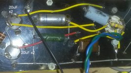
The amp itself is a single tube amplifer (or so I thought!) powered off a mains transformer, with a selenium diode rectifier and two filtering capacitor cans containing a total of four 20uF capacitors between them.
Now the circuit itself has HT, however, when I came to fault find... I found that there was HT on pin 4 of the D9 socket... which traditionally should only be around 6-7volts. Further, the 6-7volts required for the heater is instead patched onto pins 5 and 6 direct from the transformer.
Now upon finding this my mind drew up two conclusions, either the tube amp required in question is of a rare variety i'm not yet aware of or the circuit has been wired up wrongly, or even still... is not an audio amp but instead from another application altogether!
One more thing I should add is that there is a resistor closing the center socket O-ring and pin 3 of the socket.
If anyone has any ideas what I may be looking at... I would appreciate your thoughts.
Thanks in advance, and regards.
I of course have done much reading from the forums as I've went and only now have come across something (odd amp) I thought I should share and possibly even get other opinions on.
The amp itself is a single tube amplifer (or so I thought!) powered off a mains transformer, with a selenium diode rectifier and two filtering capacitor cans containing a total of four 20uF capacitors between them.
Now the circuit itself has HT, however, when I came to fault find... I found that there was HT on pin 4 of the D9 socket... which traditionally should only be around 6-7volts. Further, the 6-7volts required for the heater is instead patched onto pins 5 and 6 direct from the transformer.
Now upon finding this my mind drew up two conclusions, either the tube amp required in question is of a rare variety i'm not yet aware of or the circuit has been wired up wrongly, or even still... is not an audio amp but instead from another application altogether!
One more thing I should add is that there is a resistor closing the center socket O-ring and pin 3 of the socket.
If anyone has any ideas what I may be looking at... I would appreciate your thoughts.
Thanks in advance, and regards.
Photos, or should we find our crystal balls? It is hard to know what someone else thousands of miles away is looking at without a picture or a crystal ball.
Hello and welcome to the forums!!
I don't know about DF96 but my crystal ball is in the shop for repairs, it kept giving me false readings of "outlook not so good". 😉
Anyway if you can't take a picture (pictures are worth a thousand words) then can you just draw up a quick schematic. Be sure to note the tube in question along with voltage measurements.
I bet you have a 50c5 amp. That little tube used 50V for the filament. Now we have a little problem here as discussion about a line operated amp like this is dangerous and I bet the moderator will not allow it. Well here is the data sheet.
http://www.r-type.org/pdfs/50c5.pdf
http://www.r-type.org/pdfs/50c5.pdf
That an amp in the UK would use a power trafo, when other indicators are for AC/DC circuitry, is not surprising. The power mains in the UK are 50 Hz./"240" V.
The exact tube type used is important. Also, the selenium rectifier is a ticking, toxic, time bomb and it must be replaced by modern silicon part(s). Resistance should be added to the circuitry, to account for the lower forward drop silicon exhibits.
It is a matter of routine to replace old, literally dried out, electrolytic capacitors.
The amp itself is a single tube amplifer (or so I thought!) powered off a mains transformer, with a selenium diode rectifier and two filtering capacitor cans containing a total of four 20uF capacitors between them.
Now the circuit itself has HT, however, when I came to fault find... I found that there was HT on pin 4 of the D9 socket... which traditionally should only be around 6-7volts. Further, the 6-7volts required for the heater is instead patched onto pins 5 and 6 direct from the transformer.
Now upon finding this my mind drew up two conclusions, either the tube amp required in question is of a rare variety i'm not yet aware of or the circuit has been wired up wrongly, or even still... is not an audio amp but instead from another application altogether!
One more thing I should add is that there is a resistor closing the center socket O-ring and pin 3 of the socket.
If anyone has any ideas what I may be looking at... I would appreciate your thoughts.
Thanks in advance, and regards.
These connections look a lot like those for a 35W4 power diode. This type was very common in all sorts of equipment that operated direct from the AC mains. The 35W4 includes a heater tap-off for panel incandescent lamps. Connections were often made between the plate and one side of the heater, so the average DC would flow through part of the heater circuit to keep that panel light on after warm-up.
Having HT on one of the heater pins wouldn't be uncommon, as that removes the voltage difference across the HK insulation. I'd need to see a schemo to know better what you're dealing with. However, it doesn't look very promising. 35W4's and PTX-less spells out CHEAP. The OPTs were horrible, and often their very limited low frequency response was actually used to suppress ripple hum.
Ironic indeed since the 50C5 spec sheet includes two sets of plate characteristics: one for the commonly operation with the plate and screen both at 110CDC and another for V2K= 90V that are quite a bit more linear (and conveniently identical to the output of the VR-90 voltage regulator tube). It looks like they were intending for quality audio applications that didn't happen back in "the day". Virtually everything that used 50C5 finals was cheap, sounded horrible, and abused 50C5s with out-of-spec operations to get more power.
why does everyone think this is live mains? He quite clearly states the unit is "powered off a mains transformer, with a selenium diode rectifier and two filtering capacitor cans".
A schematic or failing that photos would help tbh...
A schematic or failing that photos would help tbh...
Hi everyone!
Many thanks for all the replies. I seem to have had a wider response than I thought I would get which is great so thanks for all the responses.
Ok i'm uploading pictures as I type... beware, they are not much to write home about and the amp in question I did not make myself, infact It has only just come into my hands and last night was the first proper session I had with it. There is no sound coming from the amp, not even any hum with or without the valve... which with HT all around I suspect could be something to do with the output transformer. Though for now, back to the valve in hand.
Now that I have had a better look and have taken pictures I can confirm after the initial glance that the heater is in the correct position (pins 4 & 5), however the other pin arrangements suggest it is not a EL84, UL84, UCL83 or anything like that. The valve I pulled from the system has no markings apart from either 89D or B9D. As the pictures are not very representable I will below list the pinout arrangement of the valve socket which I hope will help further: -
pin1 - Sig input from potentiometer (0.11v DC)
pin2 - o/p transformer via passive components (0v)
pin3 - o/p transformer parallel with a 20uF FC (345v DC)
pin4 & 5 - Heater (7.8v AC)
pin6 - o/p transformer, no other connects (348v DC)
pin7 - Grounded via capacitor (0v)
pin8 - 20uF FC via a resistor (92v DC)
pin9 - Joins pin8, res, FC - but via a cap (288v DC)
I hope all this info can help with regards to determine the valve type.
If anyone needs further info... I will do my utmost.
Again, many thanks to all.
Attachments


Last edited:
Yes, thanks.
Though how best do I go about determining the valve? There are traces of markings i'm struggling to read but just can't make out, this is with good light / magnifying glass... just there is not enough there to see unfortunately.
Thanks
B9D may mean that the valve was made by Mullard in Blackburn in 1959. It is the date code part of a Philips factory code.aardvarkash10 said:B9D is the valve basing type
Probably an ECL82
Mona
Hi Ketje,
Thanks for the suggestion.
ECL82 @ The Valve Museum
Looking into the data for the ECL82 I can certainly see the anode matching with HT... but pin 3 of the circuit is connected to one of the filter caps via a resistor and also gives HT. The ECL82 data likes pin3 to be held at ground.
It's a near match... almost!
Thanks
ECL86 has it's screen grid on pin 3 ?
Mona
Would it be at 345 (DC) volts?
Pin 3 in the circuit (without the valve) is connected to a 20uF filter cap and the O/P transformer... the line is 345 volts.
Thanks for you help.
A couple of pics of the valve itself would remove a lot of uncertainty. Detail of the internal connections near the base of the valve can also help a lot with identification.
For that kind of tubes the voltage max. is 300V.But it's not abnormal that the voltage goes up without any consuption t.i. no tube in the circuit.Would it be at 345 (DC) volts?
Pin 3 in the circuit (without the valve) is connected to a 20uF filter cap and the O/P transformer... the line is 345 volts.
Thanks for you help.
Mona
Hey,
Thanks again to all for the replies.
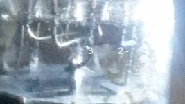
Attached below are a couple of pictures inside the valve, numbering each best I could.
It seems 1 and 2 are attached internally (2 being shorter). 6 & 7 go straight down. 3 & 9 curl as they go down, and 1 not only has a connection straight down but also curls near to where 9 is.
I have also since took the chance to test the speaker / output transformer earlier today... the speaker was 3.5 ohms, 2nd coil was about 1 ohm and the 2nd coil was 305 ohms... so nothing too abnormal there, though having said.. maybe the 2nd could have been a little lower.
Thanks again for all the help.
Thanks again to all for the replies.
Attached below are a couple of pictures inside the valve, numbering each best I could.
It seems 1 and 2 are attached internally (2 being shorter). 6 & 7 go straight down. 3 & 9 curl as they go down, and 1 not only has a connection straight down but also curls near to where 9 is.
I have also since took the chance to test the speaker / output transformer earlier today... the speaker was 3.5 ohms, 2nd coil was about 1 ohm and the 2nd coil was 305 ohms... so nothing too abnormal there, though having said.. maybe the 2nd could have been a little lower.
Thanks again for all the help.
Attachments
- Status
- Not open for further replies.
- Home
- Amplifiers
- Tubes / Valves
- An Amp oddity