Hi! New guy here -- thanks for having me! 🙂
I'm fairly new to the world of electronics, and the most ambitious project I've completed to date has been performing the Lyle Mods to my Marshall Class 5 amp. (Successfully, even!)
But I got the bug bad. 🙂 My copy of Morgan Jones' Valve Amps book isn't even here yet, but I've already gotten started...
I've salvaged an old Capehart-Farnsworth AM/FM Radio & Phonograph to do my first salvage amp creation. So far, there's a lot that's very familiar. But, of course, this didn't start life as a guitar amp so there's some oddball stuff, too.
The good news is I got a power transformer, output transformer, Alnico speaker, and tubes and bases for a rectifier, pre-amp, and output tube.
Plus a lot of caps and resistors which may or may not be very useful -- and a pile of other junk that certainly isn't.
I've studied the schematic and stripped it down to what I think are the bare bones of what a very basic guitar amp would need. Like so:
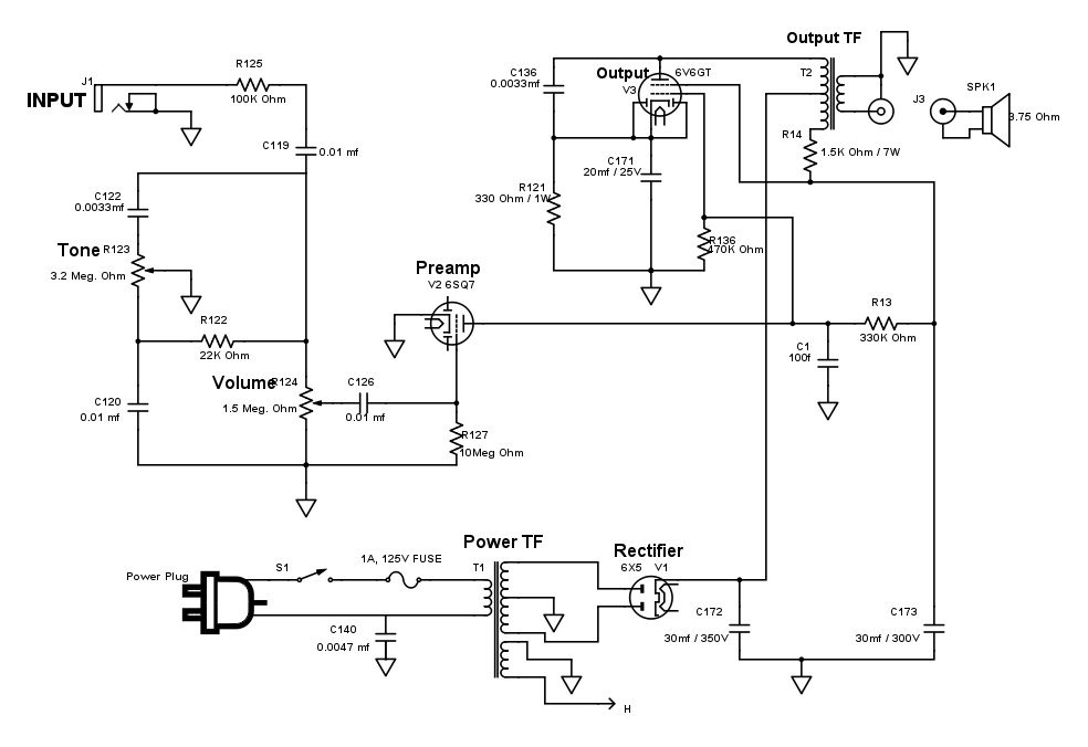
Now, I'll freely admit I've completely cribbed this off of C-F's original schematic. Aside from a LOT of deletions, and adding an input jack, I haven't changed anything. While I had some wacky ideas about making this into something it isn't, I really don't need to buy a bunch of new parts when this might not work at all, and also -- these parts DID work well enough together at one point. I'm not likely to blow out this fragile speaker* or burn up the OT or whatever, by sticking with this layout.
[* -- The speaker is a nice big 12". But it is LIGHT, with a very small alnico magnet and about a 1" or so voice coil. I don't think I'll be rattling the windows too badly with this one. But it might sound cool for late night practice...]
But the cap and resistor values I see in the tone stack don't look like numbers I'm familiar with. I see 3.2 Meg. Ohms on the tone pot. Wow. And about half that on the volume pot. I know the screened frequencies cut out by these will be a function of both the resistance and capacitance in the circuit, but is this even close to right for a guitar?
And what about moving the tone stack in front of the pre-amp? I didn't, but wouldn't that give me control closer to the final product?
I sure do appreciate any thoughts, comments, warnings, improvements, suggestions, or just well-wishes. 🙂
Thanks!
I'm fairly new to the world of electronics, and the most ambitious project I've completed to date has been performing the Lyle Mods to my Marshall Class 5 amp. (Successfully, even!)
But I got the bug bad. 🙂 My copy of Morgan Jones' Valve Amps book isn't even here yet, but I've already gotten started...
I've salvaged an old Capehart-Farnsworth AM/FM Radio & Phonograph to do my first salvage amp creation. So far, there's a lot that's very familiar. But, of course, this didn't start life as a guitar amp so there's some oddball stuff, too.
The good news is I got a power transformer, output transformer, Alnico speaker, and tubes and bases for a rectifier, pre-amp, and output tube.
Plus a lot of caps and resistors which may or may not be very useful -- and a pile of other junk that certainly isn't.
I've studied the schematic and stripped it down to what I think are the bare bones of what a very basic guitar amp would need. Like so:
Now, I'll freely admit I've completely cribbed this off of C-F's original schematic. Aside from a LOT of deletions, and adding an input jack, I haven't changed anything. While I had some wacky ideas about making this into something it isn't, I really don't need to buy a bunch of new parts when this might not work at all, and also -- these parts DID work well enough together at one point. I'm not likely to blow out this fragile speaker* or burn up the OT or whatever, by sticking with this layout.
[* -- The speaker is a nice big 12". But it is LIGHT, with a very small alnico magnet and about a 1" or so voice coil. I don't think I'll be rattling the windows too badly with this one. But it might sound cool for late night practice...]
But the cap and resistor values I see in the tone stack don't look like numbers I'm familiar with. I see 3.2 Meg. Ohms on the tone pot. Wow. And about half that on the volume pot. I know the screened frequencies cut out by these will be a function of both the resistance and capacitance in the circuit, but is this even close to right for a guitar?
And what about moving the tone stack in front of the pre-amp? I didn't, but wouldn't that give me control closer to the final product?
I sure do appreciate any thoughts, comments, warnings, improvements, suggestions, or just well-wishes. 🙂
Thanks!
Attachments
Sam:
Welcome to DIY audio!
Rebuilding old gear into guitar amps can be a lot of fun.
Do you want to keep as much of the original wiring as possible ? (e.g. around the tone and vol controls, and on the tube bases)..
Or have you stripped the chassis already?
It might be more 'predictable' (but perhaps less fun) to just copy a known circuit that uses a 6V6 and octal preamp tube (5C1 Champ or 5B2/5C2 Princeton or one of the simple Supro/Valco amps- see link below). With the right octal tube you have the possibility of two preamp gain stages...
I'm not sure we mean the same thing by 'in front of'....do you mean 'before' or 'after' in the signal path?
I think putting the tone and volume to work on an amplified signal helps with the signal/noise ratio (?) -IMO the less wiring between the input jack and the first preamp tube grid, the better in terms of hum/noise.
A couple of minor details with your schematic jump out- it looks like you have the input jack wiring opposite to 'traditional' - you have the tip grounded and the ring connected to the signal path - which would need an isolated jack to make it work at all.
I'd also 'lose' the cap to ground from the AC input wiring (so-called 'death cap'), or you could replace it with a Y2-rated 'safety cap'.
The wiring around the 6V6 is a bit 'beyond me'...hopefully some more expert eyes will show up soon...🙂
Welcome to DIY audio!
Rebuilding old gear into guitar amps can be a lot of fun.
Do you want to keep as much of the original wiring as possible ? (e.g. around the tone and vol controls, and on the tube bases)..
Or have you stripped the chassis already?
It might be more 'predictable' (but perhaps less fun) to just copy a known circuit that uses a 6V6 and octal preamp tube (5C1 Champ or 5B2/5C2 Princeton or one of the simple Supro/Valco amps- see link below). With the right octal tube you have the possibility of two preamp gain stages...
An externally hosted image should be here but it was not working when we last tested it.
And what about moving the tone stack in front of the pre-amp? I didn't, but wouldn't that give me control closer to the final product?
I'm not sure we mean the same thing by 'in front of'....do you mean 'before' or 'after' in the signal path?
I think putting the tone and volume to work on an amplified signal helps with the signal/noise ratio (?) -IMO the less wiring between the input jack and the first preamp tube grid, the better in terms of hum/noise.
A couple of minor details with your schematic jump out- it looks like you have the input jack wiring opposite to 'traditional' - you have the tip grounded and the ring connected to the signal path - which would need an isolated jack to make it work at all.
I'd also 'lose' the cap to ground from the AC input wiring (so-called 'death cap'), or you could replace it with a Y2-rated 'safety cap'.
The wiring around the 6V6 is a bit 'beyond me'...hopefully some more expert eyes will show up soon...🙂
Hi!
Thanks for the great advice! 🙂
Doh! Input jack...last thing I put down on the schematic. Was probably completely dazed by that point! LOL.
And the death cap? 🙂 I figured someone would suggest that. The original design shows TWO, just in case you have the plug in backward, I guess. They wanted to make sure they got ya! I'll delete that.
This is a stripped chassis. I had to do a lot of pruning just to get rid of broken and now useless parts and the original chassis is much larger than I'll need, and with way too many big holes in it. I'm using it for now to mock up my new circuit and see if it works, but if I like any of the sounds I (hopefully) get out of it, I'll build a new box for it and do a nice clean job.
Regarding the tone stack, yes, the original radio/phono amplifier as built by Capehart-Farnsworth had the tone circuit all before the preamp tube. It seems to me that folks figured out that it was better to put them between the preamp and output tubes (or somewhere after the preamp, in multi-tube designs), but I'm too much of a neophyte to know if that would be a simple change here of if there's some reason that wouldn't work with these tubes, or this design.
Regarding different amp designs, yes, I've considered just going to something that's a lot more common. I'm hesitating because I don't really know anything about this output transformer, and certainly not the delicate looking speaker. I don't really want to blow them up, as replacing them would mean this build cost money...and for now I'm avoiding spending much cash on this experiment. Besides, I'm curious to see just what these components sound like together.
Hopefully I can soon learn how to calculate what the circuit is putting out and how much those parts can take.
I REALLY agree with VictoriaGuy here. The circuit you have here is a seriously dated design, besides the obvious crossed connections here and there. The input section looks to be have been made for a SUPER high-impedance source, like a piezo cartridge. Besides the fact that your guitar most likely has its own volume and treble controls, it would act as an antenna. If the thing didn't pick up radio transmissions, it would be very susceptible to spurious noise.
Once upon a time, the 6sq7 was a very common tube, used in All American 5 tube radios. It is roughly equivalent to half of a 12ax7 dual triode electrically. Due to their abundance, they and a few other radio tubes found their way into other pieces of equipment. The diodes in the 6sq7 should be tied to the cathode, much like the 6v6 in your picture is. Other than that, I would definitely wire the tube up like an early fender tweed. The high-impedance, grid-leak bias setup doesn't react well to being driven by a strong input signal.
I don't know what to say about the output stage. It looks to be supplying source voltage to the preamp stage through the opposite end of the output transformer. It is also DC coupled straight to the plate of the preamp tube. I hope someone who knows better can explain how this works without oscillating.
I wouldn't worry a whole lot about the original design of the circuit, as an early tweed champ is most likely a 20 year leap in technology in comparison. Obviously the power supply, the 6v6, the output transformer, and the speaker were originally matched with each other, so modifying how they connect will not put you in danger of blowing something up. As long as you keep the 6v6 biased in its "happy range", you have only gains in performance to be had over the stock rig. Most likely, you have parts laying around, ripped out of other parts of the chassis, that can be used to rewire the beast into a proper guitar amplifier you will be happy playing music through. If not, resistors and capacitors are pretty darn cheap, and the more you buy at once, the cheaper they are each.
Last edited:
Ahhh, I'd forgotten to ask about those diodes. I'd already been thinking about tying them to the cathode, but wasn't sure.
I'm happy enough to turn this into a totally different design, if that's better.
If the output stage can't keep up, well, I'll have a learning moment, eh? 🙂
I'm happy enough to turn this into a totally different design, if that's better.
If the output stage can't keep up, well, I'll have a learning moment, eh? 🙂
I don't know what to say about the output stage. It looks to be supplying source voltage to the preamp stage through the opposite end of the output transformer. It is also DC coupled straight to the plate of the preamp tube. I hope someone who knows better can explain how this works without oscillating.
I did a quick re-draw of part of the schematic to try to 'see' it better...
I'm not sure but it looks like half the OT primary is just used in the power supply circuit?
I agree that it's DC-coupled - I can't see that working without a coupling cap between the preamp and the 6V6 grid. Those 'diode-looking' connections inside the 6V6GT symbol on the schematic might be the shield connection on the old metal 6V6 ??
I'd also think about putting a resistor in the B+ line between those caps toward the preamp tube plate.
If the chassis is already stripped, I'd go with something like the Supro schematic I linked in my first post, or an early Fender.
I agree that a handful of new resistors and caps and perhaps a pot or two, would give a lot better chance at success - $20 or so for a lot of 'play value' -building (troubleshooting) and using it- vs using that design as a starting point. There wouldn't be any problem with using the OT (primary 'top half'??) and the speaker in any 6V6 SE circuit, I think. And the power supply should be OK as a start? If the radio/phono has been used regularly, it's surprising how well some of those old electrolytics hold up. (I'd replace 'em, though.)
The schematic shows the heater pins on the sockets wired to have one side grounded (IME, one pin bent down and soldered straight to the chassis is common).....perhaps they soldered a wire between the heater pin and one of the ground lugs on the tube socket, which would be nice if a different heater scheme was wanted.
I just got home with an old radio/phono, so I need to go do some dismantling myself!🙂
Attachments
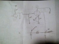
Hmmm... good point, I think.I did a quick re-draw of part of the schematic to try to 'see' it better...
I'm not sure but it looks like half the OT primary is just used in the power supply circuit?
Yeah, I can see that.I agree that it's DC-coupled - I can't see that working without a coupling cap between the preamp and the 6V6 grid.
Heh, yeah, see the drawing program I'm using didn't have a real 6V6 symbol, so I grabbed one for a generic twin diode tetrode and just grounded the two diodes, which seems like kind of what would really happen in a 6v6 with its beam forming plates tied to the cathode...sort of.Those 'diode-looking' connections inside the 6V6GT symbol on the schematic might be the shield connection on the old metal 6V6 ??
Did something similar for the 6SQ7 -- used a generic twin diode triode image.
Ok!I'd also think about putting a resistor in the B+ line between those caps toward the preamp tube plate.
I'm really leaning that way.If the chassis is already stripped, I'd go with something like the Supro schematic I linked in my first post, or an early Fender.
Yes! I'm looking at this as I've got what seems like an ok PT (maybe a little odd with just two secondaries) and rectification and output tubes handled. Might be able to make the OT and speaker fly, if I don't go too nuts. And there's this odd old design preamp tube which I might keep, or which I might replace with a 12ax7.I agree that a handful of new resistors and caps and perhaps a pot or two, would give a lot better chance at success - $20 or so for a lot of 'play value' -building (troubleshooting) and using it- vs using that design as a starting point.
(If I did replace it with a 12ax7, I'd gain a gain stage, too... wonder if that'd be pushing the output side too far?)
Well, I'm hoping. 🙂 There's the question of doubling up gain, going from the 6sq7 to a 12ax7, but I don't have to do that.There wouldn't be any problem with using the OT (primary 'top half'??) and the speaker in any 6V6 SE circuit, I think.
Yeah. All the tubes had one side of the heater jumpered to a ground lug on the tube socket.The schematic shows the heater pins on the sockets wired to have one side grounded (IME, one pin bent down and soldered straight to the chassis is common).....perhaps they soldered a wire between the heater pin and one of the ground lugs on the tube socket, which would be nice if a different heater scheme was wanted.
Oh, awesome! 🙂 It's fun! Good luck getting some useful parts out of it!I just got home with an old radio/phono, so I need to go do some dismantling myself!🙂
It's fun! Good luck getting some useful parts out of it!
Well, it's good practice de-soldering (so I tell myself)....
I usually try to figure out the B+ and the PT voltages before I take anything apart, and this one is the usual 1950 style with a hefty PT to light up a bunch of octal heaters and fairly low HT winding. Sometimes a SS bridge is needed to get the HV B+ up .
And those little OTs are just the thing for 'vintage tweed' sound! 🙂
Let us know what you decide to do with your project.
BTW, if there's some decent shielded wire from the phono input, you can use some of that in the early signal chain in the guitar amp.
C1 doesn't look right? What is that for?
Also you need a coupling cap between the pre-amp and power amp tubes. You can't put B+ from the preamp into the grid of the power amp tube.
Also you need a coupling cap between the pre-amp and power amp tubes. You can't put B+ from the preamp into the grid of the power amp tube.
Here's a schematic of the type of signal path your circuit should follow.
The component values are not super critical, I might use the 1.5 megohm pot for a volume control instead of 100k, and leave some of the existing components in the chassis (where they belong), just to get the unit making good noise. The diode bridge on the filament supply is also an option I might omit.
I have a feeling that unless you want a really clean sounding rig, you will probably end up adding another gain stage to get into the crunch or lead territory, along with some eq circuitry. Or you can put pedals in between the instrument and amp. Hopefully there is enough extra space inside the chassis you have for expansion later.
An externally hosted image should be here but it was not working when we last tested it.
The component values are not super critical, I might use the 1.5 megohm pot for a volume control instead of 100k, and leave some of the existing components in the chassis (where they belong), just to get the unit making good noise. The diode bridge on the filament supply is also an option I might omit.
I have a feeling that unless you want a really clean sounding rig, you will probably end up adding another gain stage to get into the crunch or lead territory, along with some eq circuitry. Or you can put pedals in between the instrument and amp. Hopefully there is enough extra space inside the chassis you have for expansion later.
Hi - a little OT... what program did you use for your schematic?
Mike
That's SchemeIt, on DigiKey's site.
http://www.digikey.com/schemeit/
To be honest, I'm not quite sure. As I said, this is mostly taken directly from the Capehart schematic from a long time ago. What they were thinking, I don't know. And I'm trying to learn what I need to know as quickly as possible.C1 doesn't look right? What is that for?
Yes, that is very clear now. Thank you!Also you need a coupling cap between the pre-amp and power amp tubes. You can't put B+ from the preamp into the grid of the power amp tube.
I'm certainly considering it. I'm just a little concerned about whether I can add a stage without overpowering my OT and speaker. That's probably a newbie question, but I'm still learning the basics.I have a feeling that unless you want a really clean sounding rig, you will probably end up adding another gain stage to get into the crunch or lead territory, along with some eq circuitry
Jeff, I understand that DC power to the filaments would make the amp quieter.
Is there anything to know besides adding the diodes and cap to rectify that (7V, for this PT) AC heater voltage?
Is there anything to know besides adding the diodes and cap to rectify that (7V, for this PT) AC heater voltage?
Last edited:
I'm attempting to figure out how to analyze (or, rather, understand and properly design) the circuit I might build without simply wiring it up and taking my chances.
Not knowing almost any of the key parameters of the equipment I'm attempting to use is proving to be "a bit" of a stumbling block.
For example, I can't find any reference materials which give specs on the transformers I recovered from that old phonograph. I've tested the PT with no load hooked up, plugged into my 122 VAC house mains, and see 6.9VAC across the heater winding and 242-0-242 across the main secondary and CT. (487 leg to leg).
I think I have it properly modeled in PSU Designer II, but truth be told, I don't know what to do with it after that! 🙂
I think 242 VAC should get me a maximum rectified voltage of something close to 342 VDC, which sounds just great for powering the 6V6.
Looking at your posted schematic, I assume the resistors (and choke) in bwtewwn the B+ source and the plate of the 6SL7 would drop me down close to the 250 VDC specified (300 max) for that tube's plate? I assume I'd want to adjust some values there to compensate for my slightly lower measured secondary voltage, right?
I'm certainly considering it. I'm just a little concerned about whether I can add a stage without overpowering my OT and speaker. That's probably a newbie question, but I'm still learning the basics.
The power to the OT and speakers really depends on the 6V6 part of the circuit.
If you deliver 'too much signal' to the 6V6 you may get more 'power tube distortion' than you want, but you won't hurt your OT and speakers.
There are plenty of amp designs with multi-stage preamps and a low-power output section which put out only a few watts (or fractions of a watt) to the speakers.
Ah, that makes sense! I was wondering if I could just put in a switch that would let me bypass a second gain stage so I could run it as a vintage clean amp (something close to what it originally would have done) or double up to a higher gain style. I guess that's sort of the two-channel idea, right?
Here's a schematic of the type of signal path your circuit should follow.
An externally hosted image should be here but it was not working when we last tested it.
Oh, another question! A 6SL7 is a dual triode, like a 12AX7. Is there something not shown in this schematic about how it's wired, or is this amp simply ignoring one half of it?
And wouldn't it be quite useful to capitalize on that extra side for more gain?
Would it make more sense, assuming I wanted to stick with octal tubes, to use my original 6SQ7 as a preamp and add a 6SL7 for a gain stage (maybe using both sides?) or to simply use the two sides of a 6SL7 for preamp and gain stage, a la a Fender champ did with a 12AX7?
Ah, that makes sense! I was wondering if I could just put in a switch that would let me bypass a second gain stage so I could run it as a vintage clean amp (something close to what it originally would have done) or double up to a higher gain style. I guess that's sort of the two-channel idea, right?
Sure, a switch would work.
- Status
- Not open for further replies.
- Home
- Live Sound
- Instruments and Amps
- Critique of Phonograph Conversion Amp Plans