Oh, another question! A 6SL7 is a dual triode, like a 12AX7. Is there something not shown in this schematic about how it's wired, or is this amp simply ignoring one half of it?
And wouldn't it be quite useful to capitalize on that extra side for more gain?
Would it make more sense, assuming I wanted to stick with octal tubes, to use my original 6SQ7 as a preamp and add a 6SL7 for a gain stage (maybe using both sides?) or to simply use the two sides of a 6SL7 for preamp and gain stage, a la a Fender champ did with a 12AX7?
I'd just re-wire that octal socket to use both sides of a dual triode for preamp gain stages...
If you search on 'octal guitar amp' you'll probably get some ideas (?octal fatness, octal madness?)
Here's the original article I took the schematic from:
6V6 HiFi project from the archives – Boozhound Laboratories
I picked it because it had a choke wired into the power supply much like yours, only a single preamp stage, and a single power amp stage, with tube diode rectifier. Yes, I believe in the original article the builder only used half of the preamp tube. Really an elegant little circuit. I would really not try to reverse engineer what you have, it will not cause you trouble at this power level. Even if severely mismatched, tubes are pretty forgiving and durable as far as electronic components go (except that they're glass bottles). I would just run what you have in front of you.
Once you have something that makes noise, it is much easier to tell if it sounds right for you. If you're scared you might blow something up, relax. No one will hate you for blowing a fuse or smoking a resistor. If you triple check everything before you plug it in, chances are it will work as well as it can. If the tone or gain isn't right for you, it is not extremely difficult to add another gain stage or even wire in a Pentode in the preamp socket. The possibilities are endless, limited only by your persistence and perseverance.
I wish you good luck and Godspeed in this project. Feel free to post some pics along the way. The eyes are watching, so to speak.
Last edited:
Here's the original article I took the schematic from:
6V6 HiFi project from the archives – Boozhound Laboratories
I picked it because it had a choke wired into the power supply much like yours, only a single preamp stage, and a single power amp stage, with tube diode rectifier. Yes, I believe in the original article the builder only used half of the preamp tube. Really an elegant little circuit.
That is a nice simple circuit.
A guitar amp usually needs more gain than a hi-fi amp designed for CD player or other 'line level' input signals.
100-200mV guitar signal vs 2V.
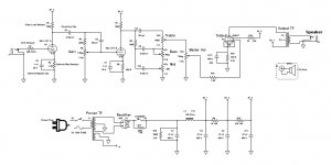
With a lot of reading over at the AX84 tube project site, and heavy borrowing, I'm thinking about something like this, then, using your octal preamp suggestions.

Lots of tone control, using both sides of a 6SL7 to add gain stage to make up for those losses, simplification of the wiring to the OT. I haven't sat down and calculated all the capacitance and resistance values yet (because I don't quite understand how*), but the wiring should be about right I think.
(* -- My copy of Morgan Jones' Valve Amps book is sitting at my local Post Office, so I'll have some heavy reading to do next week. 🙂 )
Attachments
One thing I haven't sorted out: Would I benefit from adding some diodes and rectifying the heater circuit and running those filaments DC? Or is that not feasible, possible, or a good idea?
You could make that work. It will be easier to troubleshoot a simpler circuit with just a single volume and tone control, though.With a lot of reading over at the AX84 tube project site, and heavy borrowing, I'm thinking about something like this, then, using your octal preamp suggestions.
I only had a quick look, but the schematic seems to have all the values for caps and resistors. The thing that is missing (which you may find in the discussion threads at AX84) is the voltages for the B+, B+2,preamp plates, HV secondary on the PT, etc.. Usually I've needed to do some 'fine tuning' of the power supply to get something close to 'right' voltages on the tubes. (Remember that Fender specified +/- 20% on values.I haven't sat down and calculated all the capacitance and resistance values yet (because I don't quite understand how*), but the wiring should be about right I think.
Your rectifier tube wiring will be different (5V heater).
(* -- My copy of Morgan Jones' Valve Amps book is sitting at my local Post Office, so I'll have some heavy reading to do next week. 🙂 )
The MJ book is certainly useful, though it is mostly hi-fi oriented, IIRC.
One thing I haven't sorted out: Would I benefit from adding some diodes and rectifying the heater circuit and running those filaments DC? Or is that not feasible, possible, or a good idea?
Some guitar amps use DC for the heaters (or the preamp tube heaters) but I wouldn't bother. Lots (millions?) of decent amps have been built with AC heaters.
You can always do DC heaters later if you are trying to solve a hum problem (though even then DC heaters wouldn't be at the top of my list).
Yeah, certainly true.You could make that work. It will be easier to troubleshoot a simpler circuit with just a single volume and tone control, though.
Yes, they are listed on the AX84 P1 schematic, but I don't know that they'd be at all accurate for my PT. That's part of what I meant by trying to calculate the values before I buy parts ... once I learn how. 😱 I'm guessing that once I calculate (or measure, more likely) what actual raw B+ voltage I'm getting, I'll then be able to figure out what values all the caps and resistors should be along the way, both for setting the B+1, 2, and 3 voltages, and for proper biasing each tube. Might want to add one of those tiny trim pots to each of the bias resistors to make that easily adjustable, but I don't know how important that would be.I only had a quick look, but the schematic seems to have all the values for caps and resistors. The thing that is missing (which you may find in the discussion threads at AX84) is the voltages for the B+, B+2,preamp plates, HV secondary on the PT, etc.. Usually I've needed to do some 'fine tuning' of the power supply to get something close to 'right' voltages on the tubes. (Remember that Fender specified +/- 20% on values.
In the original Capehart-Farnsworth schematic (that my PT and rectifier are taken out of), the 6X5-GT filament is wired in parallel with all the other heater filaments, right off of a leg of the heater secondary winding. That gives me 6.9V, measured on the bench with no load.Your rectifier tube wiring will be different (5V heater).
Checking the data sheets for the 6V6, 6X5, and 6SL7 they all want 6.3V and if wired in parallel the total resistance should be 4.667 ohms. I don't measure resistances that high on the 6V6 and 6X5 I have here, but not astronomically off.
Is there something I'm missing about this, that I couldn't just wire the heaters of these three tubes in parallel, like C-F did?
Last edited:
Thanks!The schematic in post #25 looks like a winner to me.
Now, I've spent the afternoon trying to teach myself to calculate appropriate plate voltages and resistor values for biasing the grids.
I'm close to admitting that I'm not qualified to teach myself any such thing! 🙂
So far the only thing I think I'm sure of is my initial B+ voltage. After that it gets confusing.
With the TMB tone stack and the master volume knob, I have a feeling you will need both gain stages. They really suck the signal.
In the original Capehart-Farnsworth schematic (that my PT and rectifier are taken out of), the 6X5-GT filament is wired in parallel with all the other heater filaments, right off of a leg of the heater secondary winding. That gives me 6.9V, measured on the bench with no load.
Is there something I'm missing about this, that I couldn't just wire the heaters of these three tubes in parallel, like C-F did?
Please ignore that reference to a 5V heater - I wasn't paying attention.
Yes, you'll be using the 6V heater string- no problem the way the C-F was wired.
🙂 Not a worry! It was a good test to help me see if I'm really starting to understand any of this stuff yet.Please ignore that reference to a 5V heater - I wasn't paying attention.
Great! I think I will make one change, though in that instead of running them the way C-F did, with a single hot wire to one leg of the filament and ground the other pin to the chassis, I'll feed them with twisted pairs to cut down on noise.Yes, you'll be using the 6V heater string- no problem the way the C-F was wired.
With the TMB tone stack and the master volume knob, I have a feeling you will need both gain stages. They really suck the signal.
Yeah. I'm considering what VictoriaGuy said about running with a simpler single volume, single tone knob arrangement. I'm just worried about being able to get pleasant tones out of it without more control. I suppose if I don't like it I could start swapping caps and resistors in the signal circuit until I land somewhere I like, but there's so much I don't know about that...
I started a build with my son last year, and it started out much like what you have laid out. Original criteria was a couple watt clean bedroom amp. It started out as a tape deck conversion with 2 preamp stages, a tone knob, and parallel 12AU7's in SE. It sounded much like a vintage Vox or an old tweed Champ.
Once it made noise, my son started playing through it daily and it was all over for that simple design. We added a TMB stack with mid sweep control first. It became "not loud enough", so the output section was changed to octal PP, eventually using one of the 12au7's as LTP phase inverter. 6K6 bottles are in the output spot now (bedroom), but the thing can run with 6V6 by just swapping tubes (garage). Then we added "presence / resonance" negative feedback controls.
I asked him last week if he was ready to close the thing up, and guess what? He said no. He has caught the disease for sure. This unit may never be completely finished. That's fine by me, it sure beats spending thousands of dollars on gear for him to figure out what sounds he likes.
Awww, man, that's an awesome story! Very encouraging! I hope my kids catch the bug. My 11 year old is a better guitarist than I am 🙂o) but actually fell asleep on the couch while I was modding our Marshall Class 5. 🙂
Great! I think I will make one change, though in that instead of running them the way C-F did, with a single hot wire to one leg of the filament and ground the other pin to the chassis, I'll feed them with twisted pairs to cut down on noise.
That's a good idea, IMO.
It also gives you more options for different ways to reduce heater hum, if that ends up being an issue.
I had good luck using a 500 ohm pot across the heater voltage. The wiper went to ground. Then you adjust the pot for minimum hum.
A lot of amps use a center tapped filament winding and then ground the center tap. That is better than tying one end to ground. If the center of the heater voltage is grounded then you have one end of the heater going + and the other end going -, so they tend to cancel out. If you tie one end to ground then the other end is all signal to get coupled into the cathode.
The pot across it does work, and helped with the hum on my Ampeg Reverberocket hum level.
- Status
- Not open for further replies.
- Home
- Live Sound
- Instruments and Amps
- Critique of Phonograph Conversion Amp Plans