I will have to go through and double check against the schematic vs the solder traces on the PCB. Also double check resistor values. I checked for solder bridges before putting power on the circuit. I must be missing a wire somewhere. Real simple stuff like that. Fresh eyes tomorrow will help - it's been a late night. A second unit would help but if it had the same problem that would be bad.
Thanks
Thanks
Also double-check pinouts on all transistors. Unless the resistor values are wildly off I doubt it'd result in zero gain. There are some on this board who may be able to look at your photos and see the error; that ain't me.
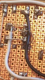
I am looking at photos now as I don't have it in front of me. I think I found the error: a missing connection from R5 & R7 to Q3 & C2+. In the backside photo if you look in upper left corner you can see right now C2+ is only connected to the bottom pin of Q3. I think I see R8 connected to the gate of Q3, but the source may not be connected. Although it may be there with a wire jumper formed by one of the resistor legs and hidden underneath be insulated wire covering that junction.
Edit: it's worse than that. Looking at high res photo I see that R8 which is supposed to be connected to Q3 base is unconnected and instead R7 is connected to the base. R5 is connected to collector of Q3, but R7 is not. I hope the transistor is not fried.
Edit: it's worse than that. Looking at high res photo I see that R8 which is supposed to be connected to Q3 base is unconnected and instead R7 is connected to the base. R5 is connected to collector of Q3, but R7 is not. I hope the transistor is not fried.
Attachments
Last edited:
Well, don't congratulate me just yet until I get it working properly. Hopefully, this is the problem. The biggest problem with point-to-point is making a mistake of incorrect connection or omission (both in my case).
Success
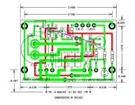
Well it was an optical illusion in my photo, upon examining the connections at Q3, they are all correct, it was just hidden at the angle shown in the photo. So what to do? I retraced all connections at all points using the circuit schematic and I found that the PCB trace diagram from the ACA pdf has an error. It shows the potentiometer leg connected to +C1, when the schematic shows that it should really be +C2. So I think the PCB trace diagram must be an earlier version, different than what went to print for the ACA PCB kits.
Anyhow, once I fixed the connection from +C1 to +C2, it works now. I am listening to it now - very nice. Not much gain though so I am using a pro-mixer preamp to boost the outputs from my source.
Here is an annotated PCB trace diagram showing the error (X) and how it should be connected (magenta line).

Someone should update the pdf or the website to fix the PCB drawing.
Well it was an optical illusion in my photo, upon examining the connections at Q3, they are all correct, it was just hidden at the angle shown in the photo. So what to do? I retraced all connections at all points using the circuit schematic and I found that the PCB trace diagram from the ACA pdf has an error. It shows the potentiometer leg connected to +C1, when the schematic shows that it should really be +C2. So I think the PCB trace diagram must be an earlier version, different than what went to print for the ACA PCB kits.
Anyhow, once I fixed the connection from +C1 to +C2, it works now. I am listening to it now - very nice. Not much gain though so I am using a pro-mixer preamp to boost the outputs from my source.
Here is an annotated PCB trace diagram showing the error (X) and how it should be connected (magenta line).
Someone should update the pdf or the website to fix the PCB drawing.
Attachments
Last edited:
Hi All,
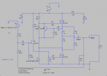
I think I've finally stumbled upon a combination that gives decent results (in simulation) using IRFP150s and 32V supply. Looks like it produces about 10W. I have no idea how this simulation will compare with reality, but I'm going to go ahead and implement these specs in my build, and see what kind of fireworks I can produce 😀
The only added component is a 2K2 resistor on the drain of Q4. Values for the other components can be seen in the schematic:

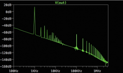
Here's the FFT:

For comparison, here's the FFT for Papa's official ACA:

I am still and forever will be an ignoramus about most of this stuff so I may be missing something huge. If so, please tell me.
I think I've finally stumbled upon a combination that gives decent results (in simulation) using IRFP150s and 32V supply. Looks like it produces about 10W. I have no idea how this simulation will compare with reality, but I'm going to go ahead and implement these specs in my build, and see what kind of fireworks I can produce 😀
The only added component is a 2K2 resistor on the drain of Q4. Values for the other components can be seen in the schematic:
Here's the FFT:
For comparison, here's the FFT for Papa's official ACA:
I am still and forever will be an ignoramus about most of this stuff so I may be missing something huge. If so, please tell me.
Attachments

I am still and forever will be an ignoramus about most of this stuff so I may be missing something huge. If so, please tell me.
Running the 2sk170's with that high a level of voltage D to S is not recommended. May I sagest you cascode it with another ZTX450. (Not actually sure if that would be called a cascode as it's not passing signal to another stage, maybe it's more proper to call it a regulator).
There is an example of how this can be done in the Pearl II Phono Stage By Wayne Colburn. You will need to change the resistor network to bring the voltage down to something like 15v.
Last edited:
Thanks LBHajdu,
The 2k2 resistor (R17 in the schem) reduced the drain voltage to ~22V. That's still too high? Would simply increasing R17 be the wrong way to go? I don't really understand cascoding, but I'll check out the Pearl II & see if I can make sense of it. Thanks again...
The 2k2 resistor (R17 in the schem) reduced the drain voltage to ~22V. That's still too high? Would simply increasing R17 be the wrong way to go? I don't really understand cascoding, but I'll check out the Pearl II & see if I can make sense of it. Thanks again...
Well ~22V would be okay, if it meets that condition at startup. However whatever voltage swing the jfet sees at R9, it sees more then double the opposite swing across R17 so there will be some miller effect. My guess is the amp will still work, but keeping the voltage at the drain of the jfet more constant would be preferred. The F5 Turbo v3 also has an example.
Hey Zennie Zenmod: Is this discrepancy that Mr. xrk971 mentions between the PCB and the schematic the Same Old Difference that people over the years have discovered and posted about? ie, It doesn't matter?
yr frd mrk
yr frd mrk
Here is an annotated PCB trace diagram showing the error (X) and how it should be connected (magenta line).
Someone should update the pdf or the website to fix the PCB drawing.
Hi xrk971,
I made the same statement ... http://www.diyaudio.com/forums/pass-labs/215392-amp-camp-amp-aca-post4525534.html#post4525534 and Kacernator answered :
Yes, you are right. PCB from Nelson Pass connects P1 directly to output capacitor, but on the schematics it goes through R3 and R4 resistors. In reality it doesn't matter, because there is only 0.5V difference across R3 and R4 resistors and P1 is there to set just voltage before output capacitor to half voltage of power supply used.
DIYAUDIO store's one doesn't follow the schematic ... mine ACA did and both are (perfectly) working 😉.
Thank You Albusine, I suspected as much. And especially helpful that you know successful builds done both ways- just like Papa and Zennie said...
So confirmed, if xrk had issues getting it to work, it isn't because of that discrepancy.
So confirmed, if xrk had issues getting it to work, it isn't because of that discrepancy.
Hi xrk971,
I made the same statement ... http://www.diyaudio.com/forums/pass-labs/215392-amp-camp-amp-aca-post4525534.html#post4525534 and Kacernator answered :
DIYAUDIO store's one doesn't follow the schematic ... mine ACA did and both are (perfectly) working 😉.
Hi,
I am new to DIY world and planning to start my first amp build with ampcamp. I have purchased few comments which is slightly deviated from original BoM. Like
BC639 instead of ZTX450
0.68ohm 2watt instead of 0.68ohm 3watt
68kohm 0.5watt instead of 68.1kohm 0.4watt
The change is not intentional. Rather it was due to the parts availability in my local store.
My question is - will this work fine? Do I need to add 100ohm with 68kohm in series to make it 68.1kohm? Does the biasing change for BC639?
Thanks,
Saikat
So confirmed, if xrk had issues getting it to work, it isn't because of that discrepancy.
Thanks for letting me now it's an old issue.
X, I think you should recheck your PCB (measuring Vgs of JFET and lower MOSFET). I'm curious because I don't believe connecting P1 to output can cause side effect, but who knows?
I think you have mentioned to purchase cheap K170 from CHN. But I don't know what could be the problem instead of different cutoff, which will lead to no conduction in JFET. But there could also be some (intermittent?) shortage around the JFET and P1 that will make the issue possible (you have mentioned that the P1 was sensitive before).
Forgot to mention that I also found that I had an incorrect value for R10. I had 330 vs 330k, off by 1000x. Everything works now and I also just implemented the 2.2k between R8 and emitter of Q3. The gain seems to have come up quite a bit and I can drive it from the headphone outs of my PC without needing a pro-mixer preamp. It sure runs hot now though and class A seems very wasteful of energy. Just not used to the amount of heat generated coming from 3 years of class D TPA311xx and TDA749x amps. Even my 200w IRS2092 which I consider on the warm side is nothing compared to this. I can keep my finger on the heatsink no longer than 6 seconds.
Sound is very nice though, but not sure if it beats Carlos' Dx amp to my ears.
I think I am going to do a amp sound blind test like I did with full range drivers. Class D TPA31xx vs class D IRS2092 vs class A ACA vs class AB Dx vs class AB LM3886. All same speaker, same mic position, adjust for same SPL at mic and post blind-labeled sound clips. It might be fun...
Last edited:
Thanks a lot @Zen Mod.just go for it , values are fine
just take care of bjt pinout
Sent from my Nexus 5 using Tapatalk
- Home
- Amplifiers
- Pass Labs
- Amp Camp Amp - ACA