Hi
I need help with a prototype development. Do I need to change something on schematic or pcb?
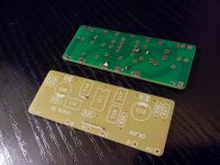
Schematic is from Sony TA-E1 preamplifier. Sony is made with SMD parts, my version is with TH parts.
I have LTspice simulation(TAE1-ccsbip.asc), and if someone can help I would be very thankful.
I need help with a prototype development. Do I need to change something on schematic or pcb?
Schematic is from Sony TA-E1 preamplifier. Sony is made with SMD parts, my version is with TH parts.
I have LTspice simulation(TAE1-ccsbip.asc), and if someone can help I would be very thankful.
Attachments
Last edited:
!
It will be completed soon!🙂
It will be completed soon!🙂
An externally hosted image should be here but it was not working when we last tested it.
An externally hosted image should be here but it was not working when we last tested it.
Attachments
Last edited:
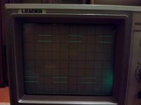
any oscillations at all? i'd be a little surprised, not seeing any small resistors in series with mosfet gates and/or base leads of diamond buffer bjts....
mlloyd1
edit: aaahhh, i see that the second schematic added mosfet gate resistors
🙂
mlloyd1
edit: aaahhh, i see that the second schematic added mosfet gate resistors
🙂
This looks like a fun little project.
I'm not sure how to import viktor's raspored.pdf PCB file into Sprint-Layout 6.
Viktor, do you have Gerber files for your PCB?
I'm not sure how to import viktor's raspored.pdf PCB file into Sprint-Layout 6.
Viktor, do you have Gerber files for your PCB?
!
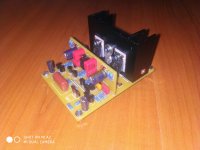
After 10 minutes of work quiescent current drops from 42mA to 31.6mA. After that there is small drop and after 53minutes from the beginning quiescent current is 29mA, after 83minutes quiescent current is 28.8mA
After 10 minutes of work quiescent current drops from 42mA to 31.6mA. After that there is small drop and after 53minutes from the beginning quiescent current is 29mA, after 83minutes quiescent current is 28.8mA
Attachments
Last edited:
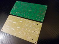
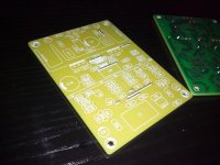
New pcb!🙂
Dear Victor,
How is your preamp running till today?
Any chance of duplicating these boards for Sony clone fans?
I need help with a TA-N901 power supply by the way.
Greetings,
Mario Gert
Sony
Hi
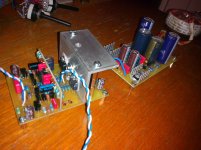
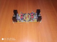
It's still in the prototype stage but I think that this is final version.
I am currently working on assembling power supply boards.
Hi
It's still in the prototype stage but I think that this is final version.
I am currently working on assembling power supply boards.
Attachments
Hi, viktor1986. Please give me the circuit and wiring of the power supply circuit board for this pre-amplifier.
viktor1986. Please tell me what is connected to the terminals + RS1, + RS2, -RS3, -RS4 in the NPS1 circuit?? How well does this work with SONY preamp? Why did you decide to build a more sophisticated power supply unit (NPS2)?
viktor1986. Please tell me what is connected to the terminals + RS1, + RS2, -RS3, -RS4 in the NPS1 circuit?? How well does this work with SONY preamp? Why did you decide to build a more sophisticated power supply unit (NPS2)?
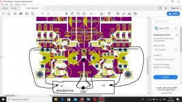
Nothing! My plan was to put remote sense wires directly on preamplifer pcb and because of that there is +RS1, +RS2...In that case, I need to cut few lines on pcb(see photo).
Forget remote sense wires(+RS1, +RS2...)...Do not cut anything and use just +V, GND and -V to connect power supply with preamplifer.
Attachments
Victor, the 2sk30GR fet seems difficult to source locally, is there an equivalent device that can be used in its place ?
Regards
Jan
Regards
Jan
Victor, I want to assemble this power supply, and I have a couple more questions for you:
I don’t understand how stabilization of the voltage at the output of the power supply occurs. And what role does the TL431 with the BD140 transistor play? I am not familiar with the inclusion of TL431.
In the circuit of transistors Q1, Q2, Q3, which are connected in parallel, I also do not see voltage-stabilizing elements. I'm just trying to understand how critical this power supply is to the input voltage (AC 24V). In what range can the input AC voltage lie?
Victor, the 2sk30GR fet seems difficult to source locally, is there an equivalent device that can be used in its place ?
Regards
Jan
I am not sure if it's equivalent transistor but you can try with 2SK170, J112, J113, BF2XX...Pay attention to the pin layout and recalculate value for R25. In general, you need 1mA CCS.
- Home
- Source & Line
- Analog Line Level
- SONY TA-E1 preamplifier clone