The cathode resistor will not reduce gain with a CCS anode load, but it will still increase output impedance.
Right. So is there degeneration? If not, you can just bypass the cathode to avoid high Zout and it will make no difference.
But is Zout is calculated the same way when you have an rk that's really a fixed voltage source? I've got to think about that one.
My poweramp has an input impedance of 68K. The 4K output impedance in conjunction with the 68K input impedance will cause a signal attenuation of 5.5%.
Keep the 1:10 rule in mind. A 4 Kohm O/P impedance is OK working into a 40 Kohm impedance and your amp's I/P impedance is 68 Kohms. Trouble is most unlikely.
If cable capacitance frightens you, make interconnects out of modest cost Mogami 2549 bulk cabling. It's capacitance at 1 KHz. is 23 pF./foot or approx. 75 pF./Meter. The Mogami stuff is shielded "twinax". You can obtain even smaller cable capacitance by using unshielded, braided, wiring. JMO, save the braided stuff for short runs in low EMI/RFI environments.
Last edited:
Good pointKeep the 1:10 rule in mind. A 4 Kohm O/P impedance is OK working into a 40 Kohm impedance and your amp's I/P impedance is 68 Kohms. Trouble is most unlikely.
If cable capacitance frightens you, make interconnects out of modest cost Mogami 2549 bulk cabling. It's capacitance at 1 KHz. is 23 pF./foot or approx. 75 pF./Meter. The Mogami stuff is shielded "twinax". You can obtain even smaller cable capacitance by using unshielded, braided, wiring. JMO, save the braided stuff for short runs in low EMI/RFI environments.
Eli, if one was to go the HV regulated power supply route why do you recommend two independent HV regulators (one per channel) instead of sharing one?
I notice John Broskie has done a CCDA with a 12B4 http://tubecad.com/2011/10/20/12B4%20CCDA.pdf. This might be interesting with a CCS plate load for the first triode and then maybe a different tube for the cathode follower.
Gain would be u/2 (edit: actually not sure if that's true with the CCS load) but a very low output impedance could be achieved.
Last edited:
Yes.dgta said:So is there degeneration?
Rk is not a fixed voltage source. It is a resistance with a nearly fixed current through it. It is the resistance which matters, not the fixed current. Bypassing the cathode resistor would have almost no effect on gain, probably little effect on distortion, and a big effect on output impedance.But is Zout is calculated the same way when you have an rk that's really a fixed voltage source?
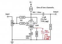
The discussion has prompted me to revise the 12B4 preamp, slightly.
FWIW, I recommend a 4.7 μF. MKP bypassed by a 0.33 μF. PPFX MultiCap as the O/P coupler. Those with "deep pockets" are (of course) free to use Mundorf or other "boutique" stuff.
When a cathode resistor bypass cap. is used, Nichicon KZ series seems obvious to me. Anyone with "Silmic", "Cerafine", or "BlackGate" on hand can, naturally, use their stock.
BTW, the CCS used depends on how awkward the downstream load is. When driving the nasty 10 Kohm IHF "standard", a cascode (FET or BJT) CCS is appropriate. Less problematic loads are "good to go" with a 10M45S CCS.
Attachments
Hi Eli,
I was planning on using the cascode MOSFET design but I also would like to incorporate the bypass cap if it reduces Zo and does not affect gain. I would like Zo as low as I can as I don't know what the preamp will be driving in the future.
How much is the bypass reducing Zo by?
If Zo is 4K when unbypassed what is Zo when Rk is bypassed?
Hi Eli,
I was planning on using the cascode MOSFET design but I also would like to incorporate the bypass cap if it reduces Zo and does not affect gain. I would like Zo as low as I can as I don't know what the preamp will be driving in the future.
How much is the bypass reducing Zo by?
If Zo is 4K when unbypassed what is Zo when Rk is bypassed?
Under the circumstances described, the O/P impedance reduces to approx. RP. I "make" that value to be about 1100 Ω. That's anything but shabby, for a common cathode circuit block. While not quite 1:10 for the fugly 10 Kohm IHF "standard", 1100 Ω is certainly adequate. Also, the 20 mA. IB allows for a good bit of cable capacitance to be handled.
Excellent!Under the circumstances described, the O/P impedance reduces to approx. RP. I "make" that value to be about 1100 Ω. That's anything but shabby, for a common cathode circuit block. While not quite 1:10 for the fugly 10 Kohm IHF "standard", 1100 Ω is certainly adequate. Also, the 20 mA. IB allows for a good bit of cable capacitance to be handled.
Two last questions if you don't mind:
1. Why do you recommend two separate regulator circuits for each CCS?
2. In your experience with this circuit what is ratio of "good" to "bad" 12B4 tubes when you bought X number of tubes?
Excellent!
Two last questions if you don't mind:
1. Why do you recommend two separate regulator circuits for each CCS?
2. In your experience with this circuit what is ratio of "good" to "bad" 12B4 tubes when you bought X number of tubes?
1. It's the pseudo dual mono mentality. The "iron" PSU is pseudo dual mono, too. Channel separation can only benefit.
2. For the most part, I get my NOS from Jim McShane. I leave the culling to an EXPERT.
If you're worried about the high output impedance just use the 'mu output' of your CCS as illustrated in post 6 linked below:
http://www.diyaudio.com/forums/tubes-valves/273502-use-mu-output-depletion-mode-mosfet-load.html
http://www.diyaudio.com/forums/tubes-valves/273502-use-mu-output-depletion-mode-mosfet-load.html
The gain is the same?If you're worried about the high output impedance just use the 'mu output' of your CCS as illustrated in post 6 linked below:
http://www.diyaudio.com/forums/tubes-valves/273502-use-mu-output-depletion-mode-mosfet-load.html
What is the output impedance now?
Google 'mu-follower' (or 'srpp'), find the formula for output impedance, then plug in your values. The result will be less than the anode impedance, but how much less depends on the details.
The gain will be the same as the conventional ccs output (your loadline is still essentially horizontal). Output impedance is approx 1/gm of the mosfet.
Last edited:
Not sure what you mean in regards to the loadline. The plate voltage is 90V and plate current is 20mA which gives a nice slope, not horizontal.The gain will be the same as the conventional ccs output (your loadline is still essentially horizontal). Output impedance is approx 1/gm of the mosfet.
If the output impedance is so low and the gain is still the same why isn't everyone employing this on their CCS plate driven stages?
This is my MOSFET http://ixdev.ixys.com/DataSheet/DS100182A(IXTY-TA-TP08N100D2).pdf
It lists Gm as 330-560 mS. So my Zo = 3-1.7 ohms? That can't be right.
Last edited:
I was assuming you were asking me to compare mu out gain to an example to conventional ccs gain. If you are using a resistor just draw the corresponding load line and determine delta Vp/delta Vg at you chosen operating point to determine gain. Then do the same for a horizontal load line and determine the ratio between the two to provide a comparison.
Chris,
One of the great things about CCS loading is a horizontal load line. CCS = constant current source or constant current sink. Constant current is the key thing.
One of the great things about CCS loading is a horizontal load line. CCS = constant current source or constant current sink. Constant current is the key thing.
Possibly because you give up high psu rejection in return. Other than that I have no idea - ask them.If the output impedance is so low and the gain is still the same why isn't everyone employing this on their CCS plate driven stages
Should read 'I was assuming you were asking me to compare mu out gain to conventional ccs gain'.I was assuming you were asking me to compare mu out gain to an example to conventional ccs gain.
Using the 'mu follower' connection won't give you 1/gm output impedance. This is because the 'follower' is not a true follower but modified. This raises the output impedance; The important ratio is valve anode impedance vs. anode resistor (the resistor driving the 'follower'). If these have the same value then you get roughly 2/gm as output impedance. Could still be low, though.
- Status
- Not open for further replies.
- Home
- Amplifiers
- Tubes / Valves
- 12B4 Preamp – Design/Pre-build Questions