I'm planning on putting together a simple amp using an LM1876, just for fun and just because a have a couple of those chips doing nothing. I'd like to make use of the 'standby' function to put it into a low power mode when not being used.
The data sheet (http://www.ti.com/lit/ds/symlink/lm1876.pdf) suggests this is pretty simple: pins 9/14 at 0V, standby off; pins 9/14 > 2.5V standby on.
On page 19, figure 45 there is a circuit for level-shifting these signals in a single-supply mode. Now I'm going to use a split-supply so I don't need to level shift, but it also shows a 100k resistor, R-shift, which it says "Additionaly R-shift limits the current supplied by the internal logic gates of the LM1876 which insures device reliability." That sounds like a good thing, whether or not you are using a split supply?
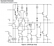
Looking at the schematic page 8, figure 6, I can see this seems sensible for the mute signal as that looks like it feeds straight to the base of a transistor (so some current limiting seems a good idea). But I'm not sure about standby - that seems to go to a 20k resistor, so I'm not certain that adding another 100k in series is such a great idea?
Any comments? Normally I'd breadboard things up and have a play, but that's not so easy in this case.
The data sheet (http://www.ti.com/lit/ds/symlink/lm1876.pdf) suggests this is pretty simple: pins 9/14 at 0V, standby off; pins 9/14 > 2.5V standby on.
On page 19, figure 45 there is a circuit for level-shifting these signals in a single-supply mode. Now I'm going to use a split-supply so I don't need to level shift, but it also shows a 100k resistor, R-shift, which it says "Additionaly R-shift limits the current supplied by the internal logic gates of the LM1876 which insures device reliability." That sounds like a good thing, whether or not you are using a split supply?
Looking at the schematic page 8, figure 6, I can see this seems sensible for the mute signal as that looks like it feeds straight to the base of a transistor (so some current limiting seems a good idea). But I'm not sure about standby - that seems to go to a 20k resistor, so I'm not certain that adding another 100k in series is such a great idea?
Any comments? Normally I'd breadboard things up and have a play, but that's not so easy in this case.
It looks like both the MUTE and the STDBY pins have internal limiters on the current. For the MUTE pin, the base current is limited by the internal constant current source in the emitter of the MUTE transistor. For the STDBY pin, the emitter current of the STDBY transistor is limited by a 20 kΩ resistor. See attached schematic (from the LM1875 data sheet).
Looks like National intended those inputs to be voltage controlled, unlike the MUTE on the LM3886 which is current controlled.
Tom
Looks like National intended those inputs to be voltage controlled, unlike the MUTE on the LM3886 which is current controlled.
Tom
Attachments
Last edited:
Thanks Tom. But I'm still a bit confused about the 'level shift' circuit in Figure 45 of the datasheet. When used with the STDBY function does this not end up with the 100k R-shift resistor in series with the pin's 20k input resistor? If so, do you not end up dropping around 5/6 of Vcc across R-shift - this would put the voltage at the pin at considerably less than the Vcc/2+2.5 you were aiming for?
But I'm still a bit confused about the 'level shift' circuit in Figure 45 of the datasheet. When used with the STDBY function does this not end up with the 100k R-shift resistor in series with the pin's 20k input resistor? If so, do you not end up dropping around 5/6 of Vcc across R-shift - this would put the voltage at the pin at considerably less than the Vcc/2+2.5 you were aiming for?
I'm not sure why you want VCC/2+2.5 V.
If you pull STDBY to VEE, the B-E junction of the PNP connected to the STDBY pin will be reverse biased hard and the transistor will be off. So the chip is out of STDBY. If you pull STDBY to VCC, the PNP turns on and disables the bias current for the input pair.
Similarly for the MUTE pin.
The 100 kΩ shown in the "level translator" is just to limit the current through the internal "logic" (the two transistors controlling MUTE and STDBY respectively) so you don't blow the B-E junctions.
I don't see any issues connecting MUTE to STDBY and driving them with the same "level translator".
Tom
I'm making final adjustments to my LM1876 amp. It's a pre-assembled board and I would like to use the standby option so I'll need to solder the pins out from the board.
I have a mains switch at the back, but would like to use a power button at the front.
Can I use a simple 5 volt line from a regulator to control the standby mode? I understood that it is a logic high input and probably doesn't like higher voltages.
If that is ok, then I'll use my power button in the front panel to control a switching relay. This relay will have 5 volt and ground inputs, and will switch between these according to the power button.
Does this sound ok? Or am I building a too complex system? Tips are welcome 🙂
Here's what the LM1876 data sheet says about it. It looks like a 5 V TTL compatible logic input. Just apply at least 2.5 V to get the chip into STDBY.
If you're using a single power supply, you'll need (VCC+VEE)/2+2.5V on the STDBY pin to engage the standby function.
Tom
If you're using a single power supply, you'll need (VCC+VEE)/2+2.5V on the STDBY pin to engage the standby function.
Tom
Attachments

- Status
- Not open for further replies.
- Home
- Amplifiers
- Chip Amps
- LM1876 and Standby Function